Modern factories no longer run on isolated machines. A single PLC controlling a conveyor or a standalone sensor reading temperature has limited value on its own. Real industrial value comes from connection, from sensors talking to controllers, controllers talking to supervisory systems, and supervisory systems feeding business platforms.
This connected approach is called the factory automation stack. Every automation project, whether it is a single production line or an entire manufacturing facility, follows this layered architecture. Engineers who understand the stack can design systems that scale, troubleshoot faster, and stay ready for future upgrades like AI and IIoT.
This guide breaks down every layer of the factory automation stack, explains how data moves through it, and shows how each piece connects to the next.
What Is a Factory Automation Stack?
A factory automation stack is a multi-layer architecture where each level performs a specific task, starting with collecting raw machine data and ending with supporting high-level business decisions.
Each layer in the stack has a clear job. A sensor does not make decisions. A PLC does not store months of production history. An ERP system does not control a motor directly. This separation of responsibility is what makes industrial systems reliable and scalable.
Why Layers Exist
Layers exist because no single system can handle every task efficiently. A PLC needs to respond to a sensor signal in milliseconds. An ERP system needs to process purchase orders and financial data that change over days or weeks. Combining these into one system would slow down real-time control and overload business software with raw machine noise.
Difference Between a Machine and an Automation System
A machine performs a physical task, like spinning a motor or closing a valve. An automation system controls, monitors, and coordinates many machines together, using sensors, controllers, networks, and software working as one unit.
How Information Flows Through the Stack
Data moves in two directions:
- Upward: raw sensor data becomes production data, then business intelligence
- Downward: business decisions become production schedules, which become machine commands
This two-way flow is what allows a factory floor to respond to real-time conditions while staying aligned with company-wide goals.
Why Modern Factories Use Layered Architecture
Layered automation architecture exists because it solves real operational problems that flat or ad-hoc systems cannot handle.
Scalability
Adding a new machine or production line does not require redesigning the entire system. Engineers add a new field device or controller into the existing layer structure.
Easier Troubleshooting
When something fails, technicians can isolate the problem to a specific layer. A communication error points to the network layer. A control issue points to the PLC layer. This narrows down root cause analysis significantly.
Standard Communication
Industrial protocols like Modbus, Profinet, and OPC UA give devices from different manufacturers a common language, so layers can exchange data without custom integration for every connection.
Vendor Interoperability
A Siemens PLC can communicate with an Allen-Bradley HMI through standard protocols. Layered design with open standards prevents factories from being locked into a single vendor ecosystem.
Better Cybersecurity
Segmenting the stack into layers allows security teams to apply different protection levels. The plant floor network can be isolated from the business network, reducing exposure to external threats.
Easier Upgrades
Replacing or upgrading a single layer, like moving from a legacy SCADA system to a modern one, does not require rebuilding the PLC logic or rewiring sensors.
Data Visibility
Each layer adds context to raw data. A temperature reading on its own means little. Once it passes through PLC logic, SCADA trending, and MES analytics, it becomes actionable production insight.
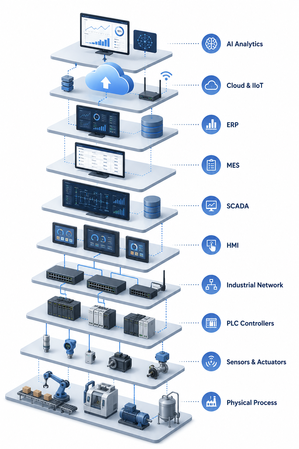
Overview of the Factory Automation Stack
Before exploring each layer in detail, here is the complete hierarchy from physical machines to business intelligence.
| Layer | Function |
|---|---|
| Physical Process | Where manufacturing physically happens |
| Sensors and Actuators | Collect data and perform physical actions |
| PLC and Controllers | Execute real-time control logic |
| Industrial Network | Move data between devices and systems |
| HMI | Let operators monitor and control machines |
| SCADA | Supervise multiple machines and lines |
| MES | Manage production execution and tracking |
| ERP | Run business operations and planning |
| Cloud and IIoT | Centralize data for analytics and remote access |
| AI and Predictive Intelligence | Turn data into predictive, optimized decisions |
This is often referred to as the ISA-95 model in industrial engineering, where each level maps to a defined scope of responsibility.
Layer 1: Physical Process
The physical process layer is where manufacturing actually happens. Every other layer exists to support, monitor, or optimize what happens here.
This layer includes the actual mechanical and electrical equipment doing physical work on the factory floor:
- Motors
- Pumps
- Compressors
- Packaging equipment
- Conveyors
- Industrial robots
Typical Industrial Examples
A bottling line filling containers, a CNC machine cutting metal parts, and a robotic arm welding car frames are all physical process examples. None of these machines understand data or logic on their own. They simply perform mechanical work based on commands from the layers above them.
Layer 2: Sensors and Actuators
Sensors collect information from the physical process, while actuators perform physical actions based on commands from the control layer.
Sensors
Sensors convert physical conditions into electrical signals that a PLC can read. Common industrial sensor types include:
- Temperature sensors
- Pressure sensors
- Proximity sensors
- Flow sensors
- Level sensors
- Vibration sensors
- Vision sensors
Actuators
Actuators take electrical signals from a controller and convert them into physical motion or action:
- Motors
- Pneumatic cylinders
- Valves
- Servo drives
- Variable Frequency Drives (VFDs)
How PLCs Interact With Sensors and Actuators
A PLC reads sensor inputs continuously, evaluates programmed logic, and sends output signals to actuators. For example, a proximity sensor detects a bottle on a conveyor, the PLC logic confirms position, and a pneumatic actuator triggers the filling nozzle.
Layer 3: PLC and Industrial Controllers
PLCs are the brains of industrial automation. They execute control logic in real time, reading inputs, processing decisions, and sending outputs within milliseconds.
How a PLC Works
- Inputs: sensor signals come into the PLC
- Logic execution: programmed instructions process the inputs
- Outputs: commands go out to actuators and other devices
- Scan cycle: this entire process repeats continuously, often within milliseconds
- Real-time control: PLCs are built specifically for deterministic, time-critical operation
Popular PLC Manufacturers
- Siemens
- Schneider Electric
- Allen-Bradley
- Mitsubishi
- Omron
- Delta
- Beckhoff
Why PLCs Are Preferred Over PCs
PLCs are built for harsh industrial environments and continuous operation. They tolerate vibration, dust, heat, and electrical noise far better than standard computers. PLCs also run deterministic logic, meaning the same input always produces the same output within a predictable timeframe, something a general-purpose PC operating system cannot reliably guarantee.
Layer 4: Industrial Communication Network
Industrial networks allow devices across the factory to exchange reliable, real-time data.
Common Industrial Protocols
| Protocol | Common Use Case |
|---|---|
| Modbus | Simple, widely supported legacy communication |
| Profinet | High-speed Siemens-based industrial Ethernet |
| EtherNet/IP | Common in Allen-Bradley and Rockwell systems |
| EtherCAT | Ultra-fast motion control applications |
| OPC UA | Cross-vendor data exchange and IIoT integration |
| CAN Bus | Automotive and mobile equipment networks |
| Profibus | Legacy fieldbus communication |
Why Industrial Communication Differs From Office Networking
Office networks prioritize bandwidth and convenience. Industrial networks prioritize determinism, low latency, and reliability. A delayed email is an inconvenience. A delayed motion command on a packaging line can cause equipment damage or safety incidents. This is why industrial protocols are engineered around guaranteed response times rather than maximum throughput.
Layer 5: HMI (Human Machine Interface)
HMI allows operators to monitor and control machines through a visual interface, without needing to read raw PLC code.
What an HMI Provides
- Dashboards showing live machine status
- Alarms for abnormal conditions
- Buttons for manual control
- Trends showing historical performance
- Recipes for repeatable production settings
- Operator permissions to control access levels
Real Production Example
On a bottling line, an operator uses an HMI screen to start the filling sequence, monitor fill levels in real time, and acknowledge an alarm when a bottle jam occurs. The HMI gives the operator visibility and control without needing to understand the underlying PLC programming.
Layer 6: SCADA Systems
SCADA supervises multiple machines, production lines, and entire facilities, sitting above individual HMIs to provide a plant-wide or even multi-site view.
What SCADA Provides
- Central monitoring across multiple production lines
- Historical data logging for long-term analysis
- Alarm management across the entire facility
- Reporting for operations and management
- Remote monitoring from outside the plant floor
- Multi-site operations for companies with several facilities
HMI Versus SCADA
| Aspect | HMI | SCADA |
|---|---|---|
| Scope | Single machine or line | Multiple machines or entire facility |
| Data Storage | Limited or none | Long-term historical logging |
| Location | On the plant floor | Plant-wide or remote |
| Primary User | Machine operator | Plant supervisor or engineer |
| Typical Use | Local control and monitoring | Facility-wide supervision |
Layer 7: MES (Manufacturing Execution System)
MES connects factory floor operations with production management, bridging the gap between real-time control and business planning.
What MES Manages
- Production scheduling
- Quality tracking
- Traceability of materials and components
- Downtime recording and analysis
- OEE (Overall Equipment Effectiveness) calculation
- Digital work instructions for operators
Industries That Rely Heavily on MES
Pharmaceutical manufacturing, automotive production, food and beverage processing, and electronics assembly all depend on MES for traceability, quality compliance, and production efficiency tracking. These industries often face strict regulatory requirements that make detailed production records essential.
Layer 8: ERP Systems
ERP manages business operations beyond the factory floor, connecting production data to company-wide planning and financial systems.
What ERP Manages
- Inventory levels across warehouses and plants
- Purchasing and procurement
- Finance and accounting
- Sales orders and customer data
- Production planning at a business level
- Supply chain coordination
How ERP Exchanges Data With MES
MES sends real production data, such as units completed and material consumed, up to ERP. ERP sends planning data, such as sales orders and material availability, down to MES. This exchange keeps business decisions grounded in actual factory performance rather than estimates.
Layer 9: Cloud, IIoT and Industrial Analytics
Cloud platforms centralize industrial data, making it accessible for analytics, reporting, and remote access beyond the physical plant.
Key Components
- IIoT gateways that connect plant floor data to cloud platforms
- Data historians that store time-series production data
- Dashboards accessible from anywhere with internet access
- Remote monitoring for engineers and managers off-site
- Energy analytics to track and reduce consumption
- Multi-plant reporting for organizations with several facilities
Edge Computing Versus Cloud Computing
Edge computing processes data locally, close to the machine, reducing latency for time-sensitive decisions. Cloud computing processes data centrally, often off-site, which works well for analytics, reporting, and long-term trend analysis where immediate response time is not critical. Many modern factories use both, applying edge computing for fast local decisions and cloud computing for broader analytics.
Layer 10: AI and Predictive Intelligence
AI transforms industrial data into predictive insights, moving factories from reactive operations to proactive decision-making.
How AI Is Applied in Manufacturing
- Predictive maintenance to forecast equipment failure before it happens
- Energy optimization to reduce consumption without affecting output
- Vision inspection to detect defects faster and more consistently than manual checks
- Demand forecasting to align production with expected sales
- Digital twins to simulate and test changes before applying them physically
- Process optimization to fine-tune parameters for efficiency and quality
Real-World Manufacturing Examples
A packaging plant uses vibration sensor data combined with AI models to predict motor bearing failure weeks in advance, scheduling maintenance before a breakdown occurs. A food processing facility uses AI-powered vision systems to detect packaging defects at a speed and consistency manual inspection cannot match.
How Data Flows Across the Entire Automation Stack
Data movement through the stack follows a consistent path, both upward and downward.
Upward Data Flow
Sensor
PLC
Industrial Network
SCADA
MES
ERP
Cloud
AI Analytics
Each step adds context. A raw sensor reading becomes a controlled process variable, then a supervised production metric, then a tracked execution record, then a business data point, then a centralized analytics input, then a predictive insight.
Downward Command Flow
Commands flow in reverse. AI insights inform business decisions in ERP. ERP generates production schedules sent to MES. MES translates schedules into work orders for SCADA and HMI. SCADA and HMI issue commands through the network to PLCs. PLCs activate actuators that move the physical process.
This constant two-way exchange is what makes a modern factory automation stack function as a connected system rather than a collection of isolated tools.
Example: Factory Automation Stack in a Bottling Plant
Walking through one production cycle shows how every layer works together in practice.
A bottle reaches the filling station, and a proximity sensor detects its position. This sensor data goes directly to the PLC.
The PLC logic confirms the bottle is correctly positioned and activates the conveyor stop mechanism. At the same time, it signals the filling actuator to begin dispensing product.
The conveyor control system pauses the line briefly during filling, then resumes once the fill cycle completes.
A flow sensor monitors the filling process in real time, ensuring the correct volume is dispensed.
A vision sensor performs quality inspection, checking fill level and cap placement before the bottle moves further down the line.
SCADA monitors this entire line alongside others in the facility, tracking throughput, flagging any anomalies, and logging performance data.
MES records this production run, updating completed unit counts, tracking the batch for traceability, and calculating OEE for the shift.
ERP receives updated inventory data as finished bottles move into the warehouse, adjusting available stock and triggering purchasing workflows if raw materials run low.
A cloud dashboard displays real-time production rates and quality metrics for managers reviewing performance remotely.
AI models analyze historical sensor data from the filling actuator, predicting when maintenance will be needed before a failure disrupts the line.
This single bottle’s journey touches every layer of the automation stack, from a basic sensor reading to a predictive AI insight.
Common Mistakes When Building an Automation Stack
Many automation projects run into avoidable problems because of decisions made early in the design process.
- No network planning, leading to bandwidth bottlenecks as devices are added
- Poor PLC architecture, making future logic changes difficult
- Ignoring cybersecurity, leaving plant networks exposed to threats
- No historian, losing valuable historical data needed for analysis
- Missing documentation, slowing down troubleshooting and onboarding
- Vendor lock-in, limiting flexibility for future expansion
- Choosing the wrong protocols, creating compatibility issues between systems
- No scalability planning, forcing costly redesigns later
How to Design a Scalable Factory Automation Stack
A scalable automation stack is built with future growth in mind from the very first design decision.
Design Principles
- Standardized architecture across all production lines
- Modular PLC programming that allows easy updates and reuse
- OPC UA integration for vendor-neutral data exchange
- Edge gateways to handle local processing before sending data to the cloud
- Cybersecurity built into every layer, not added as an afterthought
- Documentation maintained continuously, not just at project completion
- Redundancy for critical systems to avoid single points of failure
- Future AI readiness, ensuring data is structured and accessible for future analytics needs
Benefits of a Well-Designed Factory Automation Stack
- Higher productivity through coordinated, automated processes
- Lower downtime through predictive maintenance and faster troubleshooting
- Better traceability for quality and regulatory compliance
- Faster troubleshooting due to clear layer separation
- Better decision-making supported by accurate, real-time data
- Energy savings through optimized process control
- Improved quality through consistent monitoring and inspection
- Easier expansion as production needs grow
- Greater ROI from systems built to last and scale
Key Takeaways
- Every automation system follows a layered architecture, from physical machines to business intelligence.
- Each layer performs a unique role while sharing data with the layers above and below it.
- Understanding the stack helps engineers design scalable, reliable, and future-ready factories.
- Integrating PLCs, SCADA, MES, ERP, IIoT, and AI creates a connected manufacturing ecosystem capable of continuous optimization.
Build a Future-Ready Factory Automation Stack with AutomatexLab
Whether you are modernizing a single production line or designing automation for an entire manufacturing facility, a well-planned automation stack is the foundation of reliable operations.
At AutomatexLab, we help manufacturers design, implement, and optimize every layer of industrial automation, from PLC programming and HMI development to SCADA systems, IIoT integration, and smart factory solutions.
Our Industrial Automation Services
- PLC programming and control logic development
- SCADA design and monitoring systems
- HMI screen development
- Industrial IoT (IIoT) integration
- Machine and process automation
- Automation system integration
- Factory automation consulting
- Industrial troubleshooting and system upgrades
- Predictive maintenance solutions
- Smart manufacturing and Industry 4.0 implementation
Planning an automation project? Get in touch with AutomatexLab to build a scalable, secure, and future-ready factory automation architecture tailored to your production goals.
Frequently Asked Questions
The factory automation stack is the layered architecture connecting sensors, controllers, networks, supervisory systems, and business platforms to enable coordinated industrial automation.
Each layer handles a specific job and passes data to the layer above it. Sensors capture raw physical data, controllers act on that data in real time, and supervisory and business systems turn it into production records, planning inputs, and long-term insights. This structure lets a single bottling line or an entire multi-plant operation run as one connected system instead of a set of disconnected machines.
The core layers are physical process, sensors and actuators, PLC and controllers, industrial network, HMI, SCADA, MES, ERP, cloud and IIoT, and AI and predictive intelligence.
Each layer builds on the one below it. The physical process layer is the actual equipment doing the work, while sensors and actuators give that equipment the ability to sense conditions and respond to commands. PLCs handle real-time control, industrial networks move that data reliably, and HMI and SCADA give people visibility and oversight. MES and ERP connect the floor to business operations, and cloud, IIoT, and AI extend that data into analytics, forecasting, and predictive decision-making. Most factories will not run all ten layers in a fully separated way, but larger or regulated operations tend to implement each one distinctly.
A PLC controls individual machines in real time. SCADA supervises multiple machines or an entire facility. MES manages production execution and tracking. ERP manages business operations like finance, inventory, and planning.
These four systems sit at different altitudes in the stack, and confusing their roles is one of the most common mistakes in automation planning. A PLC operates on a millisecond timescale and only cares about the equipment directly wired to it. SCADA operates on a plant-wide timescale, pulling data from many PLCs to give operators and engineers a centralized view. MES operates on a shift or batch timescale, tracking what was produced, by whom, and to what quality standard. ERP operates on a business timescale, days to months, managing things like purchase orders, financial reporting, and demand planning. None of these systems are interchangeable, and a factory missing one of these layers usually has a visible gap, such as no traceability without MES or no real-time control without a PLC.
SCADA aggregates data from multiple PLCs across machines or production lines, giving supervisors a broader view than any single PLC can provide on its own.
A PLC only knows about the inputs and outputs wired directly to it. It has no awareness of what is happening on the line next to it or in another part of the building. SCADA sits above this layer specifically to solve that limitation, pulling data from many PLCs at once and presenting it as a unified picture. This is also why SCADA systems handle historical logging and facility-wide alarm management, tasks that require visibility across more than one machine. Without SCADA, plant managers would need to check each PLC or HMI individually to understand overall production status.
ISA-95 is an industry standard model that defines how levels of automation, from field devices to business systems, should integrate and exchange data within a manufacturing enterprise.
The standard breaks operations into defined levels, typically numbered from the physical process at the bottom to business planning at the top, and specifies what kind of data should move between each level. ISA-95 exists because, before standardization, manufacturers built custom integrations between every layer, which made systems expensive to maintain and difficult to scale. By following ISA-95, companies can integrate MES and ERP systems from different vendors using a shared data model, which significantly reduces integration time and long-term maintenance costs. Most modern MES and ERP platforms reference ISA-95 directly in their data exchange specifications.
IIoT sits between the plant floor and the cloud, using gateways to collect data from PLCs, sensors, and SCADA systems and transmit it to cloud platforms for analytics and remote access.
IIoT is not a replacement for PLCs or SCADA. It is an additional data path that runs alongside existing control systems, pulling a copy of relevant data without interfering with real-time control. This is an important distinction for safety and reliability, since IIoT gateways are typically read-only with respect to control logic. They collect, format, and forward data, but they generally do not issue commands back into the control layer unless specifically architected to do so with strict safeguards.
Yes, smaller operations can function without MES, but they lose detailed production tracking, traceability, and OEE calculation that larger or regulated facilities typically require.
Without MES, a factory often falls back on manual logs, spreadsheets, or basic SCADA reporting to track production. This works for smaller shops with simple products and low regulatory burden. It becomes a serious limitation in industries like pharmaceuticals, food processing, or automotive manufacturing, where traceability from raw material to finished product is a compliance requirement, not just an efficiency nice-to-have. As production volume or product complexity grows, the manual tracking that worked without MES tends to break down, which is usually the point where companies decide to implement one.
AI analyzes historical and real-time data to predict equipment failures, optimize energy use, improve quality inspection, and support smarter production planning decisions.
AI does not replace PLCs, SCADA, or MES. It works on top of the data these systems already generate. Predictive maintenance models, for example, depend on historical sensor data collected through PLCs and stored through SCADA historians or MES records. Without clean, structured data from the lower layers, AI models have little to work with, which is why factories with weak data collection often see disappointing results when they jump straight to AI projects without first solidifying their automation stack.
There is no single best protocol. OPC UA works well for cross-vendor integration, EtherCAT suits high-speed motion control, and Modbus remains common for simple, legacy device communication.
The right protocol depends on the specific requirement at that point in the stack rather than a single universal standard. A facility might use EtherCAT for synchronized motion control on a packaging line, Modbus for communicating with a simple legacy sensor, and OPC UA for sending aggregated data up to SCADA, MES, or cloud platforms. Choosing a protocol usually comes down to three factors: the speed requirement of the application, the age and compatibility of existing equipment, and whether data needs to move across different vendor ecosystems.
Cloud platforms typically connect to PLCs through IIoT gateways or edge devices that translate industrial protocol data into formats cloud systems can process, store, and analyze.
A PLC does not communicate directly with a cloud platform in most cases. Instead, an edge device or gateway sits between them, reading data from the PLC using an industrial protocol like OPC UA or Modbus, then converting and forwarding that data to the cloud using internet-friendly protocols like MQTT or HTTPS. This setup keeps the PLC isolated from direct internet exposure, which matters for both reliability and cybersecurity, while still giving cloud platforms the data they need for dashboards, analytics, and remote monitoring.