Industrial automation projects fail not because of bad hardware choices, but because of poor system architecture. A PLC system designed without scalability or modularity in mind becomes a liability the moment someone asks: “Can we add another production line?”
This guide covers everything you need to build PLC systems that grow with your operation, cut maintenance costs, and survive the next decade of process changes.
What Is PLC Scalability?
PLC scalability is the ability of a control system to expand in capacity, functionality, or complexity without requiring a complete redesign.
A scalable PLC system lets you add I/O modules, connect new equipment, support additional communication protocols, and grow your software logic without tearing apart what already works. It is not just about buying a bigger PLC. It is about designing the entire system so growth is planned from the start.
Key characteristics of a scalable PLC system:
- Additional I/O modules can be added without rewiring existing infrastructure
- Software architecture accommodates new equipment without rewriting core logic
- Communication backbone supports additional nodes and protocols
- Processing headroom exists in the CPU for future program expansion
- Network architecture handles increased traffic without redesign
Real example: A packaging machine starts as a single-line operation with 64 I/O points. Two years later, the client needs three lines and remote monitoring. A scalable design from day one means that expansion takes weeks, not months, and costs a fraction of a full rebuild.
What Is PLC Modularity?
PLC modularity means designing control systems using independent, reusable functional blocks where each block handles one specific machine function.
Instead of writing one massive program that controls everything, a modular approach breaks the system into self-contained units. Each module handles its own logic, alarms, status reporting, and diagnostics. Modules can be reused across projects, tested in isolation, and updated without affecting the rest of the system.
Core principles of modular PLC design:
- Each machine function lives in its own independent code block
- Modules share standardized interfaces so they can connect cleanly
- A problem in one module does not cascade into others
- New equipment gets its own module that plugs into the existing framework
Practical module examples:
| Module Type | What It Controls |
|---|---|
| Motor Control Module | Start, stop, fault, runtime hours |
| Valve Control Module | Open, close, feedback, timeout alarms |
| Conveyor Module | Speed, direction, jams, E-stop integration |
| Pump Module | On/off, flow feedback, cavitation detection |
| Alarm Module | Priority routing, acknowledgment, history logging |
Why Scalability and Modularity Matter in Industrial Automation
Poor PLC design is expensive. Not upfront, but over time, every modification becomes a debugging project, every expansion requires hiring the original programmer, and every fault takes hours to trace.
Reduced engineering costs come from reusing modules across machines and projects. A motor control block written once gets deployed hundreds of times. That is not theoretical. In real projects, modular code libraries cut new project programming time by 30 to 50 percent.
Faster expansions happen because the architecture already expects growth. Adding a new conveyor section means dropping in a pre-built conveyor module, wiring it to a remote I/O rack, and configuring a few parameters. No redesign.
Easier troubleshooting is the most immediate operational benefit. When every motor runs through the same standardized block, every technician knows exactly where to look when a fault occurs. Fault isolation drops from hours to minutes.
Better team collaboration becomes possible when the codebase is organized. Multiple engineers can work on different modules simultaneously without stepping on each other’s work.
Reduced downtime results from the combination of faster fault isolation, simpler software updates, and cleaner documentation. When a line goes down at 2 AM, the on-call technician can find the problem fast.
Common Mistakes in PLC Design That Kill Scalability
Most PLC systems become unmanageable over time because of a handful of repeatable mistakes. Recognizing them early is the fastest way to avoid them.
Hardcoded Logic
Writing fixed values directly into rungs instead of using parameters or tags. A timer set to T#5s buried in a rung with no label will be wrong after the next process change, and nobody will know where to find it.
Single Massive Program
Putting all logic into one Program Organization Unit with thousands of rungs. This is the most common mistake in small and mid-size PLC projects. It works at commissioning and becomes a maintenance nightmare within 18 months.
No Standard Naming Convention
Tags named things like “Bit1”, “Output7”, or “TempVar” tell the next programmer nothing. In a plant with 2,000 I/O points, bad tag naming turns every fault diagnosis into a search operation.
Excessive Cross References
Logic that jumps across multiple programs with tangled dependencies makes it impossible to understand what controls what. Module isolation requires clean interfaces, not shared variables scattered everywhere.
Poor Documentation
Undocumented function blocks, no revision history, no explanation of timing assumptions. Documentation is not optional in industrial systems. It is part of the deliverable.
Ignoring Future Expansion
Designing exactly to the current spec with no headroom in I/O, memory, or network capacity. Every experienced automation engineer has seen a panel with a rack that has no open slots left and a CPU running at 92% memory.
Best PLC Design Principles for Scalability
Start With Future Expansion in Mind
Before writing a single rung, answer these questions:
- Will additional machines or stations be added within five years?
- Will remote monitoring or IIoT connectivity be required?
- Will production speeds increase, requiring faster scan times?
- Will the client integrate with MES or ERP systems later?
- Will the system need to communicate with equipment from multiple vendors?
The answers shape hardware selection, network architecture, and software structure before the project starts. Retrofitting for scalability after the fact is always more expensive than planning for it upfront.
Use Modular Hardware Architecture
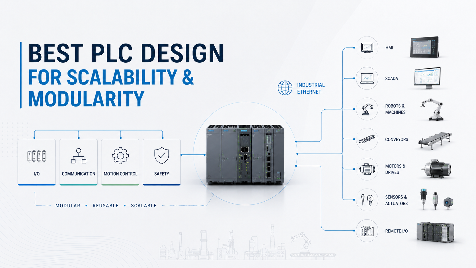
A well-structured hardware design follows a clear hierarchy:
Field Level: Sensors, actuators, motors, and drives. These connect to I/O modules.
Control Level: PLC processors and remote I/O systems. Remote I/O racks located near machine sections reduce wiring costs and improve fault isolation.
Supervisory Level: HMI panels and SCADA systems. These pull data from the control layer and present it to operators.
Enterprise Level: MES, ERP, and analytics platforms. These connect through OPC UA, REST APIs, or database connectors.
Each layer communicates with the layers directly above and below it. No layer should skip a level or create dependencies that bypass this hierarchy.
Select PLC Platforms With Expansion Capability
Not all PLCs expand equally. When evaluating platforms for scalable projects, check:
- Maximum I/O count per CPU
- Available memory for program and data storage
- Supported communication protocols (Ethernet/IP, Profinet, Modbus TCP, OPC UA)
- Remote I/O options and maximum distance
- Programming language support (Ladder, Structured Text, Function Block)
- Availability of expansion modules for motion, safety, and process control
Leave at minimum 30% spare I/O capacity and 25% spare CPU memory at project completion. That buffer is not waste. It is the cost of not doing a redesign in two years.
Best PLC Programming Practices for Modularity
Create Reusable Function Blocks
Function blocks are the foundation of modular PLC programming. Each function block encapsulates the logic for one device type or machine function. It receives inputs, processes them, and delivers outputs through a defined interface.
Standard function blocks every modular library needs:
- Motor Control Block: Handles start commands, stop commands, interlock inputs, fault detection, and runtime tracking
- Valve Control Block: Manages open/close commands, position feedback, timeout alarms, and failure detection
- PID Control Block: Contains setpoint, process variable, output, tuning parameters, and mode selection
- Alarm Handling Block: Routes alarms by priority, manages acknowledgment states, and logs to historian
Once a motor control block is proven, it gets reused across every motor in the project. Bugs get fixed once and the fix applies everywhere. Improvements get added once and benefit the entire system.
Develop Equipment-Oriented Programming
Organize software around physical machine sections, not control functions. Instead of grouping all motor logic in one program and all valve logic in another, group all logic for each machine section together.
Example structure for a process plant:
Program: ConveyorSection
  FB: Conveyor_01
  FB: Conveyor_02
  FB: ConveyorAlarms

Program: MixingSection
  FB: Mixer_01
  FB: Agitator_01
  FB: MixingValves
  FB: MixingAlarms

Program: FillingSection
  FB: FillValve_01
  FB: WeighCell_01
  FB: FillingAlarms
When a fault occurs on the filling line, the engineer opens FillingSection and finds everything they need. No hunting across programs.
Use User-Defined Data Types (UDTs)
UDTs let you define a structured data type once and use it everywhere. Instead of creating 20 separate tags for each motor (run command, stop command, fault bit, runtime hours, speed reference), you define a MOTOR_DATA UDT that contains all of them, then instantiate it for each motor.
Benefits of UDTs in modular design:
- Standardized data structures across every project
- Easier HMI development because data organization is consistent
- Faster new project starts because the library already exists
- Simpler data historian configuration
- Cleaner OPC UA tag trees for enterprise integration
Designing a Modular PLC Architecture
Layer Structure
A properly designed modular architecture separates the system into four functional layers, each with a defined role and clean interfaces to adjacent layers.
Layer One: Field Devices
This is the physical layer. Sensors, actuators, motors, drives, and safety devices. Field devices connect to I/O modules in the control layer. Nothing in this layer makes decisions. It only measures and acts.
Layer Two: Control Layer
PLC processors and remote I/O systems live here. This layer executes all control logic, runs the scan cycle, handles safety functions, and communicates with the supervisory layer. Remote I/O panels placed near machine sections keep field wiring short and fault isolation clean.
Layer Three: Supervisory Layer
HMI systems and SCADA servers. This layer handles operator interaction, alarm display, trend logging, and production reporting. It does not execute control logic. It reads from and writes to the control layer through defined communication channels.
Layer Four: Enterprise Layer
MES, ERP, analytics, and cloud platforms. This layer handles production scheduling, quality reporting, OEE tracking, and business intelligence. Connectivity from this layer into the control layer should pass through the supervisory layer, not directly into PLCs, to protect control system security.
PLC Tag Naming Standards for Scalable Systems
Tag naming is not an administrative detail. It is a technical requirement for any system that will be maintained by more than one person.
Why Naming Standards Matter
When a fault occurs at 3 AM and a technician is reading live tags on an HMI, the tag name either tells them exactly what they are looking at or it forces them to chase documentation to understand it. In a 2,000-point system with poor naming, fault diagnosis time doubles or triples.
Recommended Naming Format
A consistent tag naming structure uses this pattern:
[Area]_[Equipment]_[Device]_[Function]
Good examples:
| Tag Name | What It Represents |
|---|---|
| PKG_CNV01_MTR_Run | Packaging conveyor 01 motor run command |
| MIX_AGT01_VLV_Open | Mixing agitator 01 valve open command |
| FIL_WGH01_PV_Weight | Filling scale 01 process variable weight |
| UTL_PMP01_FLT_Fault | Utility pump 01 fault status |
Bad examples:
| Tag Name | Problem |
|---|---|
| Motor1Run | No area, no equipment ID |
| Bit37 | Completely meaningless |
| TempOutput | Temporary variables left in production code |
| XV_001 | Instrument tag format without context |
Modular Alarm Management Design
Alarm management is where most PLC systems fail in operation. Poorly designed alarm systems flood operators with nuisance alarms, causing alarm blindness and real faults getting missed.
Alarm Categorization
Critical Alarms: Require immediate operator action. Machine stops or process at risk. Examples: E-stop activated, safety door open, over-temperature shutdown.
Warning Alarms: Require attention within minutes. Process degraded but running. Examples: Filter pressure high, motor temperature elevated, low material level.
Information Alarms: Status messages. No action required. Examples: Batch complete, shift changeover, scheduled maintenance due.
Centralized Alarm Handling
Route all alarms through a centralized alarm function block or alarm server. This gives you:
- Consistent alarm formatting across the entire system
- Centralized acknowledgment logic
- Automatic alarm logging without programming it separately for each device
- Easy alarm rationalization and auditing
Alarm Reusability Strategy
Each equipment module handles its own alarms internally and passes them to the central alarm handler through a standardized alarm array. Adding a new piece of equipment means its alarm logic is already built into its module. No separate alarm configuration required.
Network Design Considerations for Scalable PLC Systems
Industrial Ethernet Architecture
Modern scalable PLC systems run on Industrial Ethernet. Flat networks where all devices share bandwidth create problems at scale. A properly designed network uses segmentation.
Recommended network segments:
- Control Network: PLC-to-PLC and PLC-to-remote-I/O communication
- HMI Network: Operator interface communication
- SCADA Network: Supervisory system communication
- Enterprise Network: MES, ERP, and analytics connectivity
- DMZ: Buffer zone between control systems and enterprise IT
Redundancy Planning
For critical systems, plan redundancy at the start, not after the first unplanned downtime event.
- Ring topology for Ethernet networks provides automatic failover
- Redundant PLC CPUs for processes where downtime costs are high
- Redundant power supplies in control panels
- Redundant communication paths between remote I/O and CPU
Cybersecurity Considerations
Control systems connected to enterprise networks or the internet require security architecture built in from the design phase.
- Firewall between control network and enterprise network
- No direct internet access to PLC systems
- Role-based access control on HMI and SCADA systems
- Regular firmware updates on all network devices
- Audit logging for all configuration changes
PLC Design Patterns Used in Large Industrial Projects
State Machine Design
State machines model machine behavior as a series of defined states with defined transitions between them. Each state describes what the machine is doing. Each transition describes the condition that moves the machine from one state to the next.
State machines make complex machine sequencing readable, testable, and maintainable. They are particularly valuable in batch processes, pick-and-place machines, and any application with multi-step sequences.
Equipment Module Pattern
Derived from ISA-88, the equipment module pattern defines a standard structure for any reusable piece of equipment: a motor, a valve, a drive, or a pump. Each equipment module contains its own control logic, alarm logic, mode management, and status reporting.
This pattern is the foundation of industrial code libraries used by major automation integrators. Once built, an equipment module library dramatically reduces programming time on all future projects.
ISA-88 Modular Design Concepts
ISA-88 is the international standard for batch process control. Its concepts apply far beyond batch processes.
The standard defines a physical model (enterprise, site, area, process cell, unit, equipment module, control module) and a procedural model (procedure, unit procedure, operation, phase). Applying these concepts to any automated system produces clean, hierarchical code that maps directly to physical equipment.
ISA-95 Integration Strategy
ISA-95 defines the integration between control systems and enterprise business systems. It defines what information flows between levels of the automation hierarchy and in what format.
Using ISA-95 as a framework ensures that data collected at the PLC level is structured in a way that MES and ERP systems can consume it without custom development work at every integration point.
Best PLC Platforms for Modular and Scalable Design
| Platform | Expansion Capability | Programming Flexibility | Communication Support | Enterprise Integration |
|---|---|---|---|---|
| Siemens S7-1500 | Excellent | Excellent (all IEC languages) | Profinet, OPC UA, Modbus | Strong (TIA Portal, MindSphere) |
| Rockwell ControlLogix | Excellent | Good (Ladder, ST, FBD) | Ethernet/IP, OPC UA | Strong (FactoryTalk suite) |
| Schneider Modicon M580 | Good | Good | Ethernet, Modbus TCP | Moderate |
| Mitsubishi iQ-R | Good | Good | CC-Link IE, Ethernet | Moderate (iQ Monozukuri) |
| Omron NX Series | Good | Excellent (IEC 61131-3) | EtherNet/IP, OPC UA | Good |
All five platforms support modular programming. The differentiator is ecosystem depth. Siemens and Rockwell have the most mature library ecosystems and enterprise integration toolsets. Mitsubishi is strong in Asia-Pacific and offers competitive pricing for mid-scale projects.
How Modular PLC Design Reduces Maintenance Costs
Faster Fault Isolation
With modular code, a fault on Conveyor 03 shows up in the Conveyor_03 function block. The technician opens that block, reads the diagnostic bits, and identifies the problem. In a flat, unorganized program, that same fault requires searching through thousands of rungs.
Easier Software Updates
Updating motor protection logic in a modular system means updating one motor control function block. The change applies to every motor in the system automatically on next download. In a non-modular system, the same change requires editing hundreds of individual rungs.
Reduced Engineering Hours
Modular systems accumulate value over time. The first project using a function block library takes normal engineering hours. The second project using the same library takes 30 to 40 percent fewer hours. By the fifth project, the library is mature, tested, and delivers consistent results.
Simplified Operator Training
When every motor behaves the same way on the HMI and every alarm follows the same format, operator training is simpler and retention is higher. Operators learn the pattern once and apply it everywhere.
Checklist: How to Build a Future-Proof PLC System
Hardware Checklist
- Minimum 30% spare I/O capacity at project completion
- Remote I/O racks positioned near machine sections
- Redundant power supplies in critical panels
- Network switches with managed ports and VLAN capability
- Spare slots in I/O racks for future expansion modules
- CPU selected with headroom for future program growth
Software Checklist
- Standardized function block library established before programming starts
- UDTs defined for all major equipment types
- Consistent tag naming convention documented and enforced
- Equipment-oriented program structure (not function-oriented)
- State machine design used for sequential processes
- All function blocks documented with input/output descriptions
Network Checklist
- Network segments defined for control, HMI, SCADA, and enterprise
- Firewall between control network and enterprise IT
- Ring topology or redundant paths for critical communication
- Remote access solution with VPN and role-based authentication
- Network documentation including IP addressing and VLAN assignments
Documentation Checklist
- Revision history maintained in all programs
- I/O list with tag names, descriptions, and wire numbers
- Network diagram with all device addresses
- Function block library documentation
- Alarm list with descriptions and response procedures
Cybersecurity Checklist
- No direct internet exposure on PLC network
- Role-based access control on all operator interfaces
- Default passwords changed on all network devices
- Firmware update schedule established
- Audit logging enabled on critical systems
Key Takeaways
- Scalability and modularity are separate concerns that both need to be designed in from the start
- Function block libraries are the single highest-ROI investment in any PLC programming practice
- Tag naming conventions, UDTs, and equipment-oriented program structure are not optional for maintainable systems
- Network segmentation and cybersecurity must be part of the architecture, not an afterthought
- Leave 30% spare I/O and 25% spare CPU capacity at project completion
- ISA-88 and ISA-95 frameworks provide proven blueprints for modular industrial automation architecture
- A well-designed modular PLC system reduces engineering hours on future projects, cuts troubleshooting time, and extends the useful life of the automation investment
FAQs
Design for modularity from the start. Use function blocks for every equipment type. Leave headroom in I/O and CPU capacity. Structure communication architecture to support additional nodes. Avoid hardcoded values and single-program designs.
Modular PLC programming organizes control logic into independent, reusable function blocks where each block handles one specific device or machine function. Each module has defined inputs and outputs, handles its own alarms and diagnostics, and can be updated or replaced without affecting other modules.
Scalability refers to hardware and system capacity growing over time. Modularity refers to software organization using independent, reusable code blocks. A well-designed system needs both: scalable hardware architecture that can grow, and modular software that makes growth manageable.
A layered architecture using distributed remote I/O, managed Ethernet networks, equipment module-based software, and supervisory SCADA connectivity. Siemens S7-1500 and Rockwell ControlLogix are the most common platforms for large-scale industrial projects in North America and Europe.
Each module is self-contained with its own diagnostic bits and alarm outputs. Fault isolation becomes a matter of identifying which module is reporting an issue rather than searching an entire program. Troubleshooting time drops significantly.
Yes. Reusable function block libraries reduce programming hours on repeat project types. Standardized alarm and tag structures reduce commissioning time. Faster troubleshooting reduces maintenance costs over the system lifetime. The investment in building a proper library pays back on the second or third project.