SCADA systems are the digital nervous system of modern industrial operations. They keep factories running, pipelines safe, water treatment plants operational, and power grids stable.
Most engineers interact with SCADA through dashboards and alarm screens. But very few understand what actually happens inside the architecture. What travels through the wires? How does a temperature reading become a visual on an operator screen? What processes handle the data in between?
This article breaks down the entire SCADA workflow layer by layer, from field sensors to enterprise dashboards, using clear and practical language.
What Happens When a Sensor Sends Data to a SCADA Screen?
The answer involves PLCs, communication protocols, industrial networks, databases, servers, alarms, historians, and real-time visualization systems working together continuously.
Every sensor reading you see on an industrial dashboard has passed through at least five distinct processing layers before reaching your eyes. Understanding those layers is what separates basic SCADA users from engineers who can design, troubleshoot, and optimize industrial systems.
What Is a SCADA System?
SCADA stands for Supervisory Control and Data Acquisition. It is an industrial monitoring and control architecture that collects real-time data from machines, processes it through PLCs or RTUs, transmits it over industrial networks, and displays it on operator dashboards for monitoring, alarms, automation, and decision-making.
SCADA is used across:
- Manufacturing plants
- Oil and gas pipelines
- Water treatment facilities
- Power generation plants
- Smart factories and Industry 4.0 environments
The key distinction in SCADA is the difference between monitoring and control. Monitoring means reading values from the field. Control means sending commands back to machines based on logic or operator decisions. SCADA handles both simultaneously in real time.
What Are the Core Layers of SCADA Architecture?
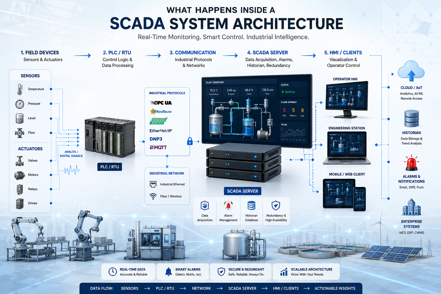
SCADA architecture is divided into five primary layers: field layer, control layer, communication layer, supervisory layer, and enterprise layer.
Each layer has a specific job. Each one depends on the one below it. Understanding this layered model is the foundation of understanding how SCADA actually functions.
The Field Layer: Where Industrial Data Begins
The field layer is where physical reality becomes digital data. Sensors and actuators form this layer.
Sensors collect physical measurements:
- Temperature
- Pressure
- Flow rate
- Tank level
- Motor speed
Actuators respond to control signals:
- Motors
- Control valves
- Relays
- Variable frequency drives
How a sensor actually sends data:
A temperature sensor detects 85°C at a process line. That physical measurement converts into an electrical signal. The most common format in industrial environments is a 4 to 20 milliamp analog signal. The 4mA value typically represents the minimum range, and 20mA represents the maximum. This signal travels through shielded cable to the PLC input module where it gets converted into a usable digital value.
Digital signals work differently. They carry binary states: on or off, open or closed, running or stopped.
Industrial signal cables use shielding and grounding to resist electromagnetic interference from motors, drives, and high-voltage equipment nearby. Reliability at the field layer directly affects everything above it in the architecture.
The PLC and RTU Layer: Industrial Processing Logic
PLCs and RTUs process sensor data, execute industrial logic, and decide how machines should respond.
This is where raw field data becomes meaningful process information.
What happens inside a PLC:
A PLC runs on a continuous loop called the scan cycle. It has four stages:
| Scan Cycle Stage | What Happens |
|---|---|
| Read Inputs | PLC reads all sensor and field device values |
| Execute Logic | Ladder logic or function blocks run against current values |
| Update Outputs | PLC sends commands to actuators based on logic results |
| Diagnostics and Communication | PLC updates communication buffers for SCADA |
This cycle runs continuously, often every 10 to 100 milliseconds. The speed and consistency of this cycle is what makes PLCs reliable for real-time industrial control.
Memory mapping and tags:
Every value inside a PLC lives at a specific memory address. A temperature value might sit at register address 40001. A motor status bit might sit at coil 00017. These addresses are mapped to tags, which are named references used by SCADA systems to identify and request specific data.
Real example:
If a tank’s water level exceeds the high limit, the PLC automatically closes the inlet valve. This happens without any operator interaction, within one scan cycle, based purely on the logic programmed into the PLC.
PLC vs RTU:
RTUs (Remote Terminal Units) function similarly to PLCs but are designed for remote and harsh environments, especially in oil and gas and utility applications. RTUs typically have better built-in communication capabilities for long-distance telemetry and work in locations without reliable power infrastructure.
How Does Industrial Communication Work in SCADA?
Industrial communication protocols transfer machine data between PLCs, SCADA servers, HMIs, sensors, and enterprise systems.
Standard IT networking protocols like HTTP or TCP were not designed with determinism in mind. Industrial environments need guaranteed delivery timing. A late packet in a factory network can mean a missed alarm or a machine running when it should have stopped.
Common SCADA communication protocols:
| Protocol | Type | Common Use |
|---|---|---|
| Modbus RTU | Serial | Legacy PLCs, sensors |
| Modbus TCP/IP | Ethernet | Modern PLCs over LAN |
| OPC UA | Ethernet | Secure cross-platform data exchange |
| Profinet | Ethernet | Siemens-based automation |
| EtherNet/IP | Ethernet | Rockwell Automation systems |
| DNP3 | Serial/IP | Utilities and SCADA telemetry |
| MQTT | IP | IIoT and cloud-connected systems |
Polling vs publish/subscribe:
Traditional protocols like Modbus use polling. The SCADA server asks the PLC for a value, the PLC responds. This happens on a schedule, sometimes every 100 milliseconds.
Modern IIoT-oriented protocols like MQTT use publish/subscribe. The PLC publishes data when a value changes. The SCADA server subscribes to that data stream and receives updates automatically. This reduces unnecessary network traffic and improves responsiveness.
Real example:
A PLC sends tank level data to the SCADA server every 100 milliseconds using Modbus TCP/IP. The SCADA server polls the specific register address, receives the 16-bit integer value, scales it into engineering units (meters or percentage), and stores it in the tag database.
What Happens Inside the SCADA Server?
The SCADA server collects industrial data, processes tags, manages alarms, stores history, and distributes information to operator screens.
The SCADA server is the central processing hub of the entire architecture. Here is what runs inside it continuously.
Data Acquisition
The server runs device drivers for each connected PLC or RTU. These drivers handle protocol-specific communication, error detection, and retry logic. If a PLC stops responding, the driver flags the tag as bad quality and triggers a communication alarm.
Tag Management
Tags are named references to specific data points. A tag named “Tank01_Level” might map to Modbus register 40005 on PLC-03 at IP address 192.168.1.10.
The tag database holds:
- Tag name and description
- Source device and register address
- Engineering units and scaling formula
- Alarm limits
- Historical logging settings
- Access permissions
A mid-size SCADA system might manage tens of thousands of tags simultaneously.
Alarm Processing
When a tag value crosses a configured limit, the alarm engine activates. Industrial alarm systems use priority levels:
- High-High: Immediate danger, requires urgent operator action
- High: Process deviation, monitor closely
- Low: Below normal range
- Low-Low: Critical low condition
Alarms also include event-based triggers, rate-of-change alerts, and deviation alarms. Alarm management is one of the most critical functions in SCADA. A poorly configured alarm system leads to alarm flooding, where operators receive hundreds of simultaneous alerts and cannot effectively respond to any of them.
Historian Database
The historian is the long-term memory of the SCADA system. It stores time-stamped process values at configured intervals or on exception (when a value changes beyond a threshold).
Historians enable:
- Trend analysis over days, months, or years
- Production performance reporting
- Root cause analysis after incidents
- Maintenance scheduling based on runtime data
Popular historian platforms include OSIsoft PI, Wonderware Historian, and Ignition’s built-in historian.
Redundancy Architecture
Production-critical SCADA systems use redundant servers. A primary server handles all active processing. A standby server mirrors the primary continuously. If the primary server fails, the standby takes over within seconds. This architecture is called hot standby redundancy.
How Do HMI Screens Actually Visualize Process Data?
HMI screens visualize industrial data from SCADA servers so operators can monitor processes and control equipment.
An HMI is not just a static picture. Every graphic element on an HMI screen is bound to a live data tag. When the tag value changes, the graphic updates automatically.
What HMI screens display:
- Tank fill levels shown as animated fill graphics
- Motor status shown as green (running) or red (stopped) indicators
- Real-time trend graphs showing value history over time
- Alarm banners with priority color codes
- Valve positions, pump speeds, and flow totals
The technical refresh workflow:
- PLC updates a register value during its scan cycle
- SCADA server polls the PLC and receives the updated value
- The tag database updates with the new value and timestamp
- The HMI client requests the current tag value
- The HMI graphic element refreshes to reflect the new value
This entire cycle typically completes within one to two seconds in a well-configured system.
Modern HMI deployment options:
- Thick client: Software installed on dedicated operator workstations
- Thin client: Browser-based HMI running on any networked device
- Web SCADA: Accessible through standard web browsers from anywhere on the network
- Mobile SCADA: Dashboards optimized for tablets and smartphones for field operators
How Does Industrial Data Travel Through the Entire SCADA Architecture?
This step-by-step example follows a water tank monitoring scenario through every layer of the SCADA architecture.
Step one: A level sensor detects water at 72% capacity and outputs a 15.5mA analog signal.
Step two: The PLC input module reads the analog signal and converts it to a scaled integer value representing 72%.
Step three: The PLC ladder logic compares 72% against configured thresholds. No alarm condition exists. The value sits within normal operating range.
Step four: The PLC stores the value in register 40012 and makes it available for communication.
Step five: The SCADA server polls the PLC via Modbus TCP every 500 milliseconds, reads register 40012, and receives 72%.
Step six: The tag “Tank01_Level” updates in the SCADA tag database with value 72% and the current timestamp.
Step seven: The HMI tank graphic refreshes. The visual fill animation updates to show 72%.
Step eight: If the level were to drop to 15%, the Low-Low alarm would trigger. The alarm banner appears on the HMI. An email or SMS notification goes to the on-call operator.
Step nine: The historian logs the value at its configured interval, creating a time-stamped record.
Step ten: The operator sees the low level alert on the HMI and clicks the start button for the inlet pump. The SCADA server sends a write command to the PLC, which energizes the pump motor output.
SCADA Network Architecture: How Industrial Networks Are Built
Industrial SCADA networks are designed around reliability, redundancy, and security rather than pure speed.
Common industrial network topologies:
| Topology | Characteristics | Use Case |
|---|---|---|
| Star | Central switch connects all devices | Standard factory networks |
| Ring | Devices connected in a loop with redundancy | Critical process networks |
| Redundant Ethernet | Dual network paths with automatic failover | High availability systems |
| Fiber optic | Immune to electrical noise, long distances | Large plant environments |
Network segmentation in industrial facilities:
Modern SCADA networks use VLANs to separate traffic by function. Control traffic between PLCs and SCADA servers stays on one VLAN. HMI traffic on another. Enterprise network access on a third. This limits broadcast traffic and reduces the attack surface for cybersecurity threats.
Industrial managed switches support features like:
- Port mirroring for traffic analysis
- Quality of service settings to prioritize control traffic
- SNMP monitoring for network health visibility
- Rapid Spanning Tree Protocol for fast failover in ring topologies
SCADA Cybersecurity: Protecting Industrial Systems
SCADA cybersecurity protects industrial systems from unauthorized access, malware, ransomware, and operational disruptions.
Industrial systems were not originally designed with cybersecurity in mind. Many legacy SCADA systems run on older operating systems without regular security patches, creating significant vulnerability.
Key cybersecurity measures in modern SCADA:
- Air gaps: Physical separation between SCADA networks and corporate IT networks
- Industrial firewalls: Packet inspection configured for OT protocols
- OPC UA security: Built-in encryption and certificate-based authentication
- VPN access: Encrypted tunnels for remote SCADA access
- Role-based access control: Operators, engineers, and administrators get different permission levels
- Zero trust architecture: Every connection verified, no implicit trust based on network location
OT vs IT security:
Operational Technology security differs from IT security in one critical way: availability comes first. In IT, you can patch a server and restart it. In OT, restarting a SCADA server might mean shutting down an entire production line. Security measures must be implemented carefully to avoid disrupting continuous operations.
Real industrial cyberattacks have targeted water treatment facilities, power grids, and manufacturing plants. The Stuxnet attack and various ransomware incidents against industrial operators demonstrate that SCADA cybersecurity is not theoretical. It is an active operational requirement.
Modern SCADA vs Traditional SCADA
| Capability | Traditional SCADA | Modern SCADA |
|---|---|---|
| Server infrastructure | Local on-premise servers | Cloud-enabled or hybrid |
| Protocol support | Proprietary vendor protocols | Open standards like OPC UA, MQTT |
| Remote access | Limited or none | Web browser and mobile apps |
| Alarm management | Basic threshold alerts | AI-assisted alarm analytics |
| Data integration | Standalone isolated system | IIoT and ERP connected |
| Scalability | Hardware-limited | Cloud-scalable |
| Analytics | Basic trending | Predictive and prescriptive analytics |
SCADA, IIoT, and Industry 4.0 Integration
Modern SCADA systems are no longer isolated industrial platforms. They are connected nodes in broader digital manufacturing ecosystems.
Cloud SCADA:
SCADA data streams to cloud platforms where it combines with enterprise data for facility-wide analytics. Cloud infrastructure allows SCADA to scale without major on-premise hardware investments.
Edge computing:
Edge devices process data locally before sending it upstream. Instead of sending every raw sensor value to a central server, edge nodes filter, aggregate, and analyze data at the source. This reduces bandwidth requirements and enables faster local decision-making.
Predictive maintenance:
Historians feed machine learning models that predict when equipment is likely to fail. Instead of waiting for a breakdown or following a fixed maintenance schedule, technicians get alerts when actual wear patterns suggest upcoming failure.
Digital twins:
A digital twin is a virtual model of a physical process. SCADA data feeds the digital twin in real time. Engineers use it to simulate process changes, test control logic, and optimize performance without touching the live production environment.
Unified Namespace:
The Unified Namespace (UNS) concept organizes all industrial data from sensors, PLCs, SCADA, ERP, and MES systems into a single, structured data broker. Every system publishes to and subscribes from the same namespace using MQTT or similar protocols.
Common Problems Inside SCADA Architecture
Understanding failure modes is as important as understanding normal operation.
Communication failures: Network issues between SCADA server and PLCs cause tags to go into bad quality state. Causes include cable faults, switch failures, IP conflicts, and protocol mismatches.
Tag mismatches: When PLC register addresses change after a code update but SCADA tag mappings are not updated, operators see wrong values or communication errors.
PLC timeout: If a PLC scan cycle takes too long or the CPU is overloaded, communication responses become inconsistent. SCADA server marks tags as stale.
Alarm flooding: Poorly designed alarm systems generate hundreds of simultaneous alerts during a process upset. Operators cannot identify which alarm actually requires action.
Network latency: High-latency networks delay data updates between PLC and SCADA server. Real-time control decisions degrade.
Server overload: Excessive tag counts, high scan rates, and insufficient server hardware cause SCADA servers to fall behind on data processing.
Poor redundancy planning: Single points of failure in network or server architecture cause complete SCADA outages when individual components fail.
Best Practices for Designing SCADA Architecture
- Use a scalable tag naming convention from day one. Tags like “Site01_Area02_Tank01_Level” are easier to manage than “T1_Lv”
- Design redundant communication paths for all critical field devices
- Segment networks using VLANs and industrial firewalls
- Implement alarm rationalization before going live. Every alarm needs a defined cause, consequence, and corrective action
- Size historian storage for at least three years of data at configured scan rates
- Test failover of redundant servers during commissioning, not after a real failure
- Document all PLC register to SCADA tag mappings and keep them version-controlled
Real Industrial SCADA Use Cases
Water treatment plants: SCADA monitors flow rates, chemical dosing, tank levels, pump operations, and water quality sensors across multiple treatment stages. Operators in a central control room manage the entire facility from a single HMI environment.
Smart manufacturing: Production lines use SCADA to track machine states, OEE (Overall Equipment Effectiveness), cycle times, and quality data. SCADA integrates with MES systems to connect production scheduling to real-time floor activity.
Oil and gas pipeline monitoring: Pipelines span hundreds of miles. SCADA uses RTUs at remote pump stations and valve sites, communicating back to central control rooms via satellite or cellular telemetry.
Solar power plants: SCADA monitors inverter outputs, string performance, grid connection status, and energy yield. Predictive alerts identify underperforming strings before they significantly impact production.
Building management systems: Commercial buildings use SCADA-based BMS platforms to manage HVAC, lighting, fire systems, and energy consumption from centralized dashboards.
The Future of SCADA Architecture
AI-driven SCADA: Machine learning models embedded in SCADA platforms will move beyond basic threshold alarms toward pattern recognition and anomaly detection. Systems will identify developing problems before they trigger traditional alarms.
Autonomous industrial systems: Advanced control loops will handle more decision-making without operator input. Operators shift from reactive control to supervisory oversight.
Cloud-native SCADA: New SCADA platforms are built from the ground up for cloud deployment. They offer elastic scalability, subscription pricing, and integration with cloud analytics services.
Unified Namespace adoption: UNS architecture is gaining traction as the standard way to structure industrial data across entire enterprises, replacing point-to-point integrations between systems.
Conclusion
SCADA is far more than dashboards and alarm screens. It is a complete industrial data architecture where every sensor value passes through multiple intelligent layers before reaching an operator or triggering an automated response.
Field sensors convert physical reality into electrical signals. PLCs process that signal data using deterministic control logic. Industrial protocols carry data across hardened networks. SCADA servers collect, tag, alarm, and historize that data. HMI screens present it in ways operators can act on.
Modern SCADA is becoming smarter, cloud-connected, and AI-assisted. But the fundamental architecture, getting reliable data from the field to decision-makers in real time, remains the core engineering challenge that SCADA was built to solve.
Ready to Modernize Your Industrial Automation System?
At AutomatexLab, we help factories, plants, and industrial businesses design smarter automation systems using PLC, SCADA, HMI, IIoT, and Industry 4.0 technologies.
Whether you need SCADA development, PLC programming, industrial troubleshooting, or complete factory automation architecture, we build practical solutions focused on reliability, scalability, and real-world operations.
Our Industrial Automation Services
- PLC Programming & Control Logic
- SCADA Development & Integration
- HMI Design & Visualization
- Industrial IoT & Remote Monitoring
- Factory Automation Consulting
- Industrial Network Architecture
- Automation Troubleshooting & Optimization
Build Smarter Industrial Systems With AutomatexLab
Transform machine data into real-time operational intelligence with scalable automation solutions designed for modern industries.
Contact AutomatexLab today to discuss your automation project.
FAQs
Sensors, PLCs and RTUs, communication networks, SCADA servers, historian databases, and HMI displays
Through industrial communication protocols including Modbus RTU, Modbus TCP/IP, OPC UA, Profinet, and EtherNet/IP.
HMI is the operator visualization interface. SCADA is the larger supervisory architecture that includes data acquisition, alarm management, historian storage, and server-side processing. HMI is one component within a SCADA system.
Yes, in some applications. Direct sensor-to-SCADA communication is possible using smart instruments and RTUs, though control capability becomes limited compared to PLC-based architectures.
Modbus TCP/IP remains the most widely deployed protocol due to its simplicity and broad device support. OPC UA is the preferred standard for modern, secure, and cross-platform SCADA implementations.
Yes. Modern SCADA systems are core components of Industry 4.0 environments. They provide the real-time operational data layer that feeds cloud analytics, digital twins, predictive maintenance systems, and enterprise integration platforms.