Ladder logic is a graphical PLC programming language that looks like electrical relay circuits. It is used to automate industrial machines and factory processes. If you work in manufacturing, maintenance, or industrial automation, understanding ladder logic is essential.
This guide breaks down how ladder logic works, why factories still use it, and gives you real examples from the shop floor.
What Is Ladder Logic?
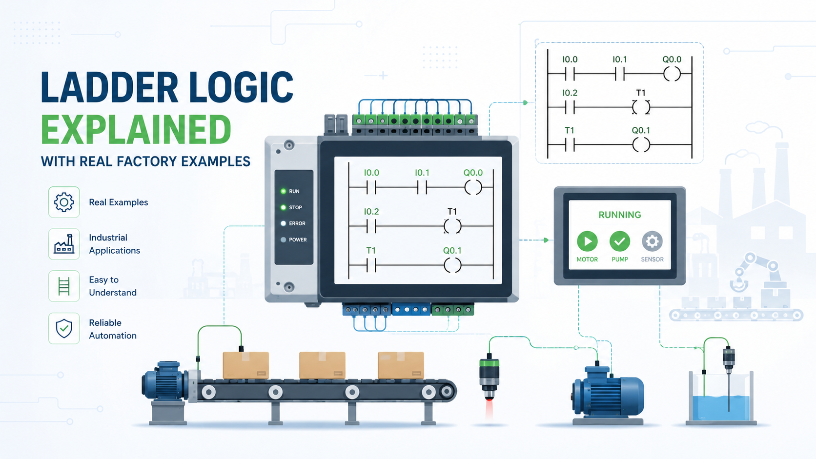
Ladder logic is a visual programming method used to control PLCs (Programmable Logic Controllers). It represents electrical relay logic in a diagram format that technicians and electricians can read and troubleshoot without writing traditional code.
It gets its name from its structure. The diagram has two vertical rails on either side, connected by horizontal rungs, just like a physical ladder. Each rung represents one control instruction or logic condition.
Why it looks familiar to electricians: Ladder logic mirrors how relay-based control panels were wired decades ago. Electricians already understood relay circuits, so the transition to PLC programming felt natural. That familiarity is one of the biggest reasons it became the dominant industrial programming language.
Ladder vs. relay wiring:
| Feature | Relay Wiring | Ladder Logic (PLC) |
|---|---|---|
| Physical components | Yes | No |
| Rewiring required | Yes | No |
| Troubleshooting speed | Slow | Fast |
| Flexibility | Limited | High |
| Cost to modify | High | Low |
How Ladder Logic Works
Ladder logic evaluates conditions from left to right on each rung. If all conditions on a rung are true, the output at the end of that rung activates. The PLC repeats this process in a continuous loop called the scan cycle.
Main Components of Ladder Logic
Input Contacts These represent real-world inputs like push buttons, limit switches, and sensors. They tell the PLC what is happening on the machine.
Output Coils These represent real-world outputs like motors, valves, and lights. When the rung logic is true, the output coil energizes.
Normally Open (NO) Contact This contact passes power only when the associated input is active. Think of it as a switch that is off by default.
Normally Closed (NC) Contact This contact passes power when the associated input is NOT active. It blocks power when triggered. Used heavily in emergency stop and safety circuits.
Timers Timers delay or limit how long an output stays active. The TON (Timer On-Delay) is the most common type in factory applications.
Counters Counters track how many times something happens. Used for counting products, machine cycles, and batch quantities.
Internal Memory Bits These are virtual contacts used inside the PLC to hold logic states without activating a physical output.
Comparison Instructions These compare values like temperatures, pressures, or counts to trigger logic conditions.
The PLC Scan Cycle
The scan cycle is the continuous loop a PLC runs to execute ladder logic. It has three stages:
- Input Scan – The PLC reads all physical input states and stores them in memory.
- Program Execution – The PLC evaluates every rung in the ladder program from top to bottom.
- Output Update – The PLC writes the results to physical outputs like motors and valves.
This cycle repeats thousands of times per second, making PLC control highly reliable for real-time machine operation.
Basic Ladder Logic Flow Example
- Operator presses the Start button
- Start contact on the rung goes TRUE
- Motor output coil energizes
- Seal-in contact holds the motor on after the button is released
- Operator presses Stop button
- Stop contact goes FALSE
- Motor coil de-energizes and motor stops
The seal-in circuit is critical for beginners to understand. Without it, the motor would only run while the start button is physically held down.
Anatomy of a Ladder Diagram
Every ladder diagram shares the same structure regardless of the PLC brand or software used.
Left Power Rail This is the vertical line on the left side. All logic starts from here and flows to the right.
Right Power Rail This is the vertical line on the right side. Output coils connect here. A rung is complete when logic flows from the left rail to the right rail.
Horizontal Rungs Each rung holds one control logic statement. Rungs are read left to right. Multiple rungs stack vertically to form the full program.
Logical Flow Direction Power flows from left to right. If any condition in the rung breaks the flow, the output does not energize.
Why Factories Still Use Ladder Logic in 2026
Factories still use ladder logic because it is reliable, easy to troubleshoot, visually readable, and supported across all major PLC platforms. No other PLC language has matched its adoption rate in industrial settings.
Benefits of Ladder Logic
Easy for Maintenance Teams Maintenance technicians do not need software engineering backgrounds. The visual format lets them trace logic quickly during breakdowns. This reduces costly downtime.
Faster Troubleshooting Most PLC software lets you monitor live ladder logic on screen. You can see which contacts are open or closed in real time while the machine is running. That capability alone saves hours during fault diagnosis.
Wide Compatibility Ladder logic runs on Siemens, Allen-Bradley, Mitsubishi, Omron, and Schneider platforms. The core concepts transfer across brands even when syntax differs slightly.
Stable for Real-Time Control Ladder logic handles time-critical machine control without delay. The deterministic scan cycle makes it predictable, which is critical for safety systems.
Limitations of Ladder Logic
Complex Systems Get Messy A large factory program with hundreds of rungs can become difficult to navigate. Without good documentation, maintenance teams struggle to understand the original programmer’s intent.
Not Ideal for Advanced Algorithms Motion control, data processing, and AI-driven logic are better handled with Structured Text or other high-level languages. Ladder logic was not designed for mathematical complexity.
Scalability Challenges As automation systems grow, ladder logic programs can become unwieldy. Large plants often use a mix of languages within the same PLC to handle different tasks.
Real Factory Example: Conveyor Belt Motor Control
Ladder logic is commonly used to start, stop, and protect conveyor motors in manufacturing plants.
The Scenario
A packaging factory runs a conveyor belt that moves products between stations. The system needs a start button, a stop button, an emergency stop, and motor overload protection.
Ladder Logic Workflow
- Operator presses the Start push button
- Motor output coil energizes
- Seal-in contact keeps the motor running after the button is released
- Conveyor belt begins moving products
- Operator presses Stop button to break the seal-in circuit
- Motor de-energizes and belt stops
- Emergency Stop button (NC contact) immediately cuts power to the motor coil
- Overload relay opens a contact in the rung if the motor draws too much current
Where This Is Used
- Automotive assembly lines
- Warehouse sorting and fulfillment centers
- FMCG packaging and labeling lines
- Food processing conveyor systems
The emergency stop always uses a normally closed contact. That means if the wiring fails or the button is not connected, the system defaults to a safe stopped state. This is called fail-safe design.
Real Factory Example: Water Tank Level Automation
The Scenario
A factory uses a large water storage tank to supply cooling and process water. Two float sensors monitor low and high levels. A pump fills the tank automatically.
Ladder Logic Sequence
- Low-level sensor activates (tank is getting empty)
- Pump output coil energizes through the low-level sensor contact
- Tank begins filling
- High-level sensor activates when tank is full
- High-level sensor contact breaks the rung logic
- Pump de-energizes and stops filling
Hysteresis logic is often added here. The pump turns on at low level and does not turn off until high level is reached. This prevents the pump from cycling on and off rapidly if the water level hovers near one sensor.
Why Factories Use This
- Eliminates the need for manual monitoring
- Prevents pump damage from dry running
- Reduces water waste from overflow
- Saves energy by running the pump only when needed
Real Factory Example: Traffic Light Control System
The Scenario
A mining or smart factory site uses a PLC to control internal vehicle traffic lights at intersections. Timing and sequence must be consistent and safe.
Ladder Logic Used
The program uses multiple TON timers on sequential rungs. Each timer controls how long one light stays active before handing off to the next rung.
- Red light output energizes and a timer starts
- When the timer completes, red light de-energizes and green light energizes
- A second timer starts for the green phase
- Yellow light activates briefly using a shorter timer
- Logic resets and the cycle repeats continuously
Industrial Applications
- Smart factory intersections
- Mining site vehicle routing
- Internal warehouse traffic management
- Loading dock access control
Real Factory Example: Bottle Filling Machine
The Scenario
A beverage production line uses a PLC to fill bottles with a precise amount of liquid. The line runs at high speed and requires sensor-based automation to stay accurate.
Ladder Logic Process
- Proximity sensor detects a bottle in the fill position
- Conveyor motor output de-energizes to stop the belt
- Solenoid valve output energizes to open the fill valve
- TON timer begins counting the fill duration
- When the timer completes, solenoid valve closes
- Conveyor motor re-energizes and moves the next bottle into position
Key Automation Components
- Proximity sensors for bottle detection
- Solenoid valves for liquid control
- TON timers for fill quantity control
- Motor starters for conveyor control
- Counter instructions to track bottles filled per batch
Real Factory Example: Automatic Door System
The Scenario
A warehouse uses a PLC to control a large automatic entrance door. A motion sensor triggers the door, and a safety sensor prevents it from closing on personnel or equipment.
Ladder Logic Flow
- Motion sensor detects movement near the door
- Door motor output energizes to open the door
- TON timer starts to hold the door open
- When the timer completes, the door motor reverses to close
- Safety sensor at the door edge activates if something is in the path
- Closing motion halts immediately and the timer resets
Common Ladder Logic Instructions Explained
| Instruction | Name | Function |
|---|---|---|
| XIC | Examine If Closed | Passes power when input is TRUE (active) |
| XIO | Examine If Open | Passes power when input is FALSE (inactive) |
| OTE | Output Energize | Activates a physical output or internal bit |
| TON | Timer On-Delay | Starts timing when rung goes TRUE |
| CTU | Count Up | Increments a counter each time rung goes TRUE |
| RES | Reset | Resets a timer or counter to zero |
| MOV | Move | Copies a value to a memory location |
| GRT | Greater Than | Compares two values, passes if first is greater |
Beginner Ladder Logic Program: Motor Start-Stop
The easiest ladder logic program is a simple motor start-stop circuit using a start push button, a stop push button, and a motor output coil.
Input and Output Assignment
| Tag Name | Type | Description |
|---|---|---|
| Start_PB | Input | Normally Open push button |
| Stop_PB | Input | Normally Closed push button |
| Motor_Out | Output | Motor contactor coil |
Rung Breakdown
Rung 1:
- Start_PB (XIC) in series with Stop_PB (XIO) connected to Motor_Out (OTE)
- Pressing Start energizes the motor
Rung 2 (Seal-in):
- Motor_Out contact (XIC) in parallel with Start_PB feeds the same rung
- Once the motor is on, it stays on even after the Start button is released
Stopping the Motor:
- Stop_PB is wired as XIO (Examine If Open)
- When the stop button is pressed, that contact opens and breaks the rung
- Motor_Out de-energizes
This three-element circuit is the foundation of every ladder logic program ever written in industrial automation.
Ladder Logic vs Other PLC Programming Languages
Ladder Logic vs Structured Text
| Feature | Ladder Logic | Structured Text |
|---|---|---|
| Format | Visual/graphical | Code-based (like Pascal) |
| Best for | Relay-style control | Math, algorithms, data |
| Maintenance | Easier for technicians | Requires coding knowledge |
| Learning curve | Low for electricians | Higher for non-programmers |
Ladder Logic vs Function Block Diagram
Function Block Diagram (FBD) uses graphical blocks connected by lines. It works well for process control and analog systems. Ladder logic is simpler for discrete (on/off) machine control. Both are IEC 61131-3 languages and can run on the same PLC.
Ladder Logic vs Sequential Function Chart
Sequential Function Charts (SFC) visualize step-by-step machine sequences. They work well for batch processes and multi-stage automation. Ladder logic handles individual step logic better, so many programs use SFC for structure and ladder logic inside each step.
Industries That Use Ladder Logic
- Automotive manufacturing – Body welding, paint lines, assembly stations
- Food and beverage processing – Filling, packaging, pasteurization
- Pharmaceutical plants – Batch mixing, clean-in-place systems
- Water treatment facilities – Pump control, chemical dosing
- Oil and gas – Pipeline valve control, compressor management
- Warehouse automation – Conveyors, sorters, palletizers
- Smart factories – Machine cells, robot integration, production tracking
Best PLC Software for Ladder Logic Programming
Popular PLC Platforms
Siemens TIA Portal Used heavily in Europe and globally. Supports ladder logic through the LAD programming environment. Strong for large integrated systems.
Rockwell Automation Studio 5000 The standard for North American manufacturing. Allen-Bradley PLCs are dominant in US automotive and consumer goods plants.
Schneider Electric EcoStruxure Common in building automation, water treatment, and energy management applications.
Mitsubishi Electric GX Works Popular in Asian manufacturing and increasingly common in US facilities. Strong for machine tool and robotics integration.
Omron CX-Programmer Widely used in packaging and food processing. Known for reliability and straightforward ladder logic programming.
What Beginners Should Start With
- Factory IO – A 3D simulation tool that connects to virtual PLCs
- RSLogix Micro Starter Lite – Free Rockwell simulation software
- Siemens S7-PLCSIM – Simulates TIA Portal programs without hardware
- OpenPLC – Free open-source PLC runtime for learning
How To Learn Ladder Logic Faster
The fastest way to learn ladder logic is by practicing real industrial examples rather than only reading theory. Simulation tools let you build and test programs without buying hardware.
Practical Learning Steps
- Start with the motor start-stop circuit and build it in a simulator
- Add an emergency stop to that same circuit
- Build a water tank automation program using timers and sensors
- Simulate a bottle counting system using counters
- Practice troubleshooting intentionally broken programs
Common Beginner Mistakes
Forgetting the Seal-In Circuit Without a seal-in contact, the motor only runs while the button is held. Most beginners make this mistake on their first program.
Incorrect Timer Configuration Setting the timer preset in seconds when the PLC expects milliseconds causes machines to behave unexpectedly. Always check the time base setting.
Poor Rung Organization Jumping between unrelated logic on the same rung makes programs hard to read. Each rung should handle one control function.
Ignoring Safety Logic Emergency stops and overload protection are not optional. Any real machine program must include fail-safe interlocks from day one.
Ladder Logic Safety Concepts
Industrial PLC programs must follow safety practices regardless of the machine size or application.
Emergency Stop Logic E-stop buttons always use normally closed contacts. If the wiring breaks, the machine stops automatically. Never use a normally open contact for an emergency stop.
Fail-Safe Programming Design your program so that any single fault causes the system to go to a safe state. Power loss should stop all motion by default.
Interlocks Interlocks prevent dangerous combinations of outputs from activating simultaneously. For example, a gate must be closed before a press cycle can start.
Motor Overload Protection Overload relays monitor motor current. Their contacts wire into the motor rung as normally closed contacts. If the motor overheats or draws too much current, the contact opens and stops the motor.
Sensor Fault Handling Programs should detect when sensors fail to change state within expected time windows. A stuck sensor that never activates can be just as dangerous as one that activates incorrectly.
Future of Ladder Logic in Smart Factories
Ladder logic is evolving alongside IIoT and smart manufacturing rather than being replaced by it.
Modern Trends
PLC and SCADA Integration Modern PLCs communicate with SCADA systems to provide real-time production data. Ladder logic still handles machine control while SCADA handles visualization and reporting.
Industrial IoT Connectivity PLCs now publish data to cloud platforms through MQTT, OPC-UA, and REST protocols. The ladder logic program continues running while data flows to dashboards and analytics systems.
Digital Twins Factory simulation tools mirror real PLC programs. Engineers can test ladder logic changes in a digital twin before applying them to the real machine.
AI-Assisted Diagnostics AI tools analyze PLC data logs to predict faults. The ladder logic program itself does not change, but AI layers on top improve maintenance scheduling and uptime.
Will Ladder Logic Be Replaced?
Not anytime soon. Here is why:
- Hundreds of thousands of existing machines run ladder logic programs
- Maintenance workforces are trained in ladder logic globally
- No other language matches its troubleshooting speed on the factory floor
- IEC 61131-3 continues to evolve ladder logic as a standard
New factories are using more Structured Text and object-oriented approaches for complex automation. But ladder logic remains the backbone of discrete machine control across every major industry in the US and worldwide.
Conclusion
Ladder logic is not a legacy technology waiting to be replaced. It is the foundation of industrial automation in the US and globally. Every conveyor, pump, press, and packaging line you see in a factory is almost certainly controlled by a PLC running ladder logic.
Understanding ladder logic means understanding how modern manufacturing actually works at the machine level. It bridges electrical engineering and software logic in a way that no other language does as cleanly.
FAQs
No. For anyone with a background in electrical work or relay circuits, ladder logic is one of the easiest programming languages to pick up. Most technicians become functional within a few weeks of hands-on practice.
A PLC is the physical hardware controller. Ladder logic is the programming language used to write the control program that runs on the PLC.
Yes. Simulators like Factory IO, RSLogix Micro Starter Lite, and OpenPLC let you build and test programs entirely in software.
Automotive, food and beverage, pharmaceutical, water treatment, and warehouse automation are the heaviest users of ladder logic in the US.
Completely. In 2026, ladder logic remains the most widely used PLC programming language in industrial automation worldwide.
Basic motor control logic takes days to learn. Becoming proficient enough to program full machine systems typically takes three to six months of consistent practice.
The Allen-Bradley Micro820 and Siemens S7-1200 are popular beginner choices. Both have free or low-cost simulation software and strong community support.