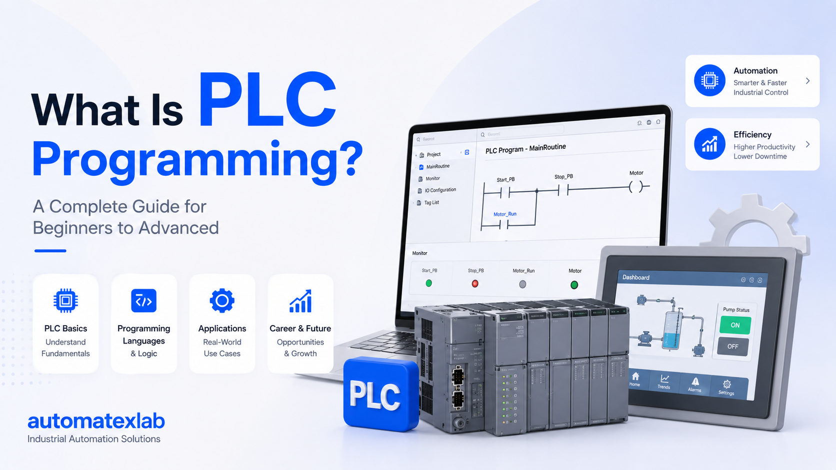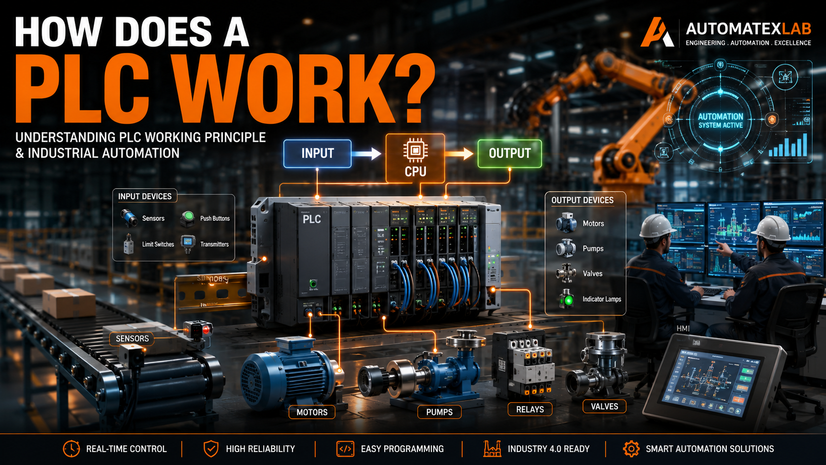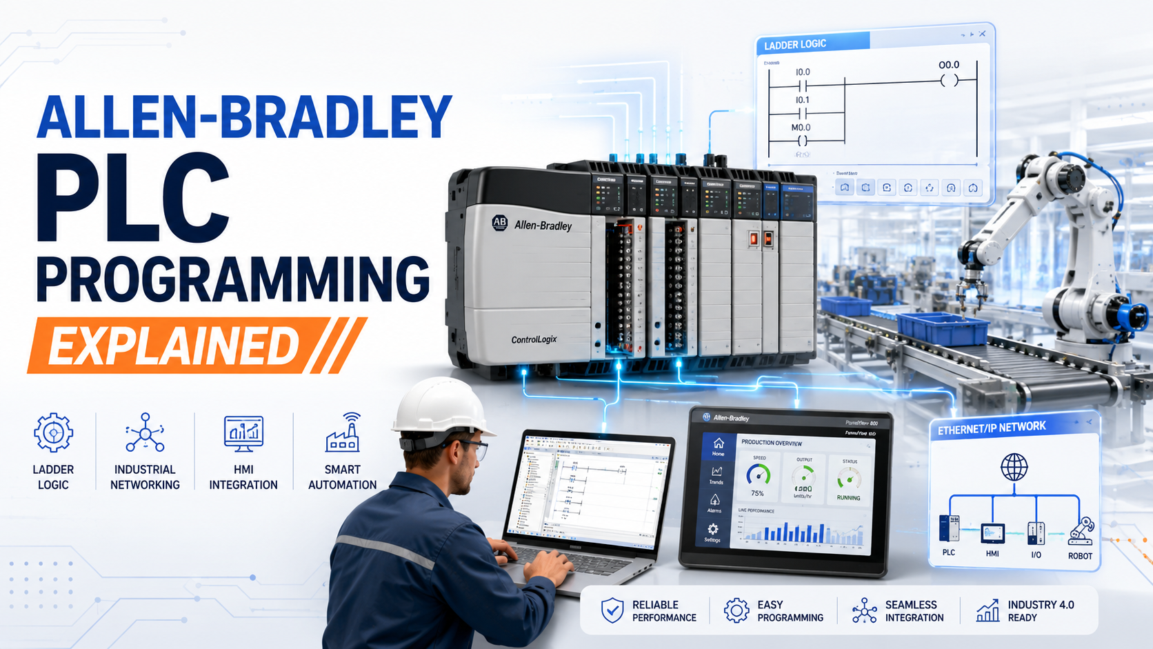
Allen-Bradley PLC programming is the process of creating control logic for programmable logic controllers manufactured by Rockwell Automation. These industrial computers control machines, processes, and entire production lines in factories worldwide.
PLCs replace thousands of physical relays with software-based logic. Instead of wiring hundreds of mechanical switches, engineers write programs that tell machines exactly what to do and when to do it.
Why Industries Choose Allen-Bradley
Allen-Bradley holds roughly 60% of the North American industrial automation market. Companies trust these controllers because they work reliably in harsh environments like dusty factories, extreme temperatures, and high-vibration settings.
The brand integrates seamlessly with other Rockwell Automation products. This ecosystem includes human-machine interfaces (HMIs), variable frequency drives, motor starters, and industrial networking equipment.
Role in Modern Manufacturing
Every automated assembly line, bottling plant, and packaging facility needs precise control. Allen-Bradley PLCs coordinate multiple machines, manage timing sequences, monitor safety systems, and communicate production data to supervisors.
A single automotive plant might use 50 to 200 PLCs controlling everything from robotic welders to paint booths to conveyor systems. Each PLC runs continuously, scanning inputs and updating outputs thousands of times per second.
What is an Allen-Bradley PLC?
Defining Programmable Logic Controllers
A PLC is an industrial computer designed to control manufacturing equipment. Unlike office computers running Windows or macOS, PLCs run real-time operating systems focused entirely on reading sensors, executing logic, and controlling outputs.
Traditional relay control panels used physical switches and timers. When a limit switch closed, current flowed through relay coils, which mechanically closed contacts to energize motors or valves. These systems required extensive wiring and were difficult to modify.
PLCs eliminated most hard-wiring. Sensors connect to input cards, motors and valves connect to output cards, and all control logic exists as software. Changing how a machine works means editing the program, not rewiring thousands of connections.
Allen-Bradley Controller Families
CompactLogix: The most popular current platform. These modular controllers fit small to medium applications. They support Ethernet/IP networking, integrate easily with HMIs, and offer excellent price-to-performance ratios.
ControlLogix: High-end controllers for large, complex processes. These chassis-based systems handle hundreds of I/O points, support redundant processors for critical applications, and coordinate multiple production areas simultaneously.
MicroLogix: Small, economical controllers for simple machines. They come as all-in-one units with built-in I/O points. Perfect for standalone equipment like small conveyors, pumps, or mixing stations.
PLC-5: Legacy platform still running in older facilities. While no longer sold, thousands remain operational. Many plants keep these running because replacing them requires complete system redesigns.
SLC 500: Another legacy line similar to PLC-5. Common in facilities built between 1990 and 2010. Parts remain available, and many companies continue supporting these proven systems.
How Allen-Bradley PLC Systems Work
The Scan Cycle
PLCs operate using a continuous scan cycle that repeats thousands of times per second. Understanding this cycle is essential for effective programming.
Step 1: Read Inputs: The processor checks every connected sensor, switch, and input device. It stores the current state (on or off, or analog values) in memory.
Step 2: Execute Logic: The processor runs through your program from top to bottom, evaluating every rung of ladder logic based on the input states it just read.
Step 3: Update Outputs: After solving all logic, the processor sends commands to output modules, turning on motors, opening valves, or updating displays.
Step 4: Communication: The processor handles network communications, exchanges data with HMIs, and updates remote I/O racks.
This entire cycle typically completes in 1 to 20 milliseconds depending on program size. Fast scan times ensure immediate response to changing conditions.
Real-World Conveyor Example
Picture a simple package sorting system. A photo eye detects packages entering the conveyor. The PLC reads this input, starts a timer, and activates the belt motor.
When the package reaches the sorting diverter (detected by a second photo eye), the PLC energizes a pneumatic cylinder that pushes the package onto the correct line. After 3 seconds, the cylinder retracts.
If the conveyor gets jammed, an emergency stop button cuts power immediately. The PLC detects this input change within milliseconds and stops all motion.
Motor Control Application
A three-phase motor requires specific start sequences. The PLC checks safety interlocks (guards closed, e-stop not pressed, no fault conditions). If all conditions are met, it energizes a contactor that supplies power to the motor.
The program monitors motor current through an analog input. If current exceeds normal limits, the PLC assumes a mechanical jam and shuts down the motor to prevent damage.
After shutdown, the PLC sets a fault bit that lights a warning lamp and sends an alert to the operator’s HMI screen.
Main Components of an Allen-Bradley PLC System
CPU and Processor Module
The processor is the brain of the system. It contains the microprocessor, memory for storing programs and data, and communication ports for programming and networking.
CompactLogix processors range from small (1769-L16ER with 512KB memory) to large (1769-L36ERM with 5MB memory). Larger memory supports bigger programs and more extensive data logging.
ControlLogix processors offer even greater capacity and support hot-swappable redundant configurations for critical applications that cannot tolerate downtime.
Power Supply Modules
PLC systems need clean, stable power. Power supplies convert standard AC voltage (120V or 240V) to the DC voltages needed by processors and I/O modules.
Industrial power supplies include surge protection, filtering, and wide operating ranges. They continue functioning despite voltage sags, spikes, and electrical noise common in factory environments.
Sizing power supplies correctly is critical. Calculate the total current draw from all modules, then add 20% margin for safety.
Input Modules
Input modules interface sensors and switches to the processor. Each module converts field signals into digital data the processor understands.
Digital Input Modules: Read on/off signals from limit switches, push buttons, proximity sensors, and photo eyes. Available in various voltage ratings (24VDC, 120VAC, 240VAC).
Analog Input Modules: Read continuous values from temperature sensors, pressure transducers, flow meters, and level sensors. These convert 0-10V or 4-20mA signals into numerical values.
High-speed counter modules track encoder pulses for position measurement. These specialized inputs handle signals arriving thousands of times per second.
Output Modules
Output modules control field devices based on program logic.
Digital Output Modules: Turn on/off motors, valves, indicator lights, and alarms. Available as relay outputs (for high-power loads) or solid-state outputs (for fast switching).
Analog Output Modules: Control variable speed drives, proportional valves, and actuators. These output 0-10V or 4-20mA signals for precise process control.
Motion control modules generate pulse trains for stepper motors and servo drives, enabling precise positioning applications.
Communication Modules
Modern manufacturing requires extensive data sharing. Communication modules connect PLCs to other devices and networks.
Ethernet/IP Modules: Standard on newer controllers. These connect PLCs to HMIs, SCADA systems, other PLCs, and enterprise networks using standard Ethernet infrastructure.
Serial Communication Modules: Connect legacy devices using RS-232, RS-485, or RS-422 protocols. Still common for interfacing older instruments and displays.
Remote I/O Adapters: Distribute I/O points across large facilities. Instead of running hundreds of wires to a central PLC, remote racks sit near machines and communicate over Ethernet.
HMI Integration
Human-Machine Interfaces provide graphical displays of process status, alarms, and controls. Operators monitor production, adjust setpoints, and troubleshoot problems through touch screens.
Allen-Bradley PanelView displays integrate seamlessly with PLCs. Programming software links HMI objects directly to PLC tags, making development straightforward.
SCADA Connectivity
Supervisory Control and Data Acquisition systems monitor entire facilities. FactoryTalk View SE (Site Edition) connects dozens or hundreds of PLCs into unified control rooms.
SCADA systems log production data, generate reports, manage recipes, and provide remote access for engineering support.
Allen-Bradley PLC Programming Software
Studio 5000 Logix Designer
This is the primary software for programming CompactLogix and ControlLogix controllers. Studio 5000 provides comprehensive development tools in one integrated environment.
The interface includes sections for organizing your project. The controller organizer shows programs, tasks, and routines. The I/O configuration section defines all connected modules. The tag database manages all variables.
Offline Programming: Develop and test programs without connected hardware. The software validates logic, checks tag references, and identifies errors before downloading to actual controllers.
Online Programming: Connect to running PLCs to monitor operation, edit logic while machines operate (carefully), and troubleshoot problems in real-time.
RSLogix 500
This legacy software programs SLC 500 and MicroLogix controllers. While older, thousands of facilities still use RSLogix 500 daily.
The interface is simpler than Studio 5000. Programs organize into ladder files, and addressing uses fixed memory locations rather than modern tag names.
FactoryTalk View Studio
Separate software for developing HMI applications. You design screens, add graphics representing equipment, create alarm displays, and program navigation between screens.
FactoryTalk View Studio links to PLC tags automatically. When you reference a tag in an HMI object, the runtime software reads/writes that tag’s value directly.
Simulation and Testing Tools
Emulate 5000: Virtual PLC software that runs controller firmware on your PC. You can test complete programs without physical hardware, simulating inputs and watching outputs respond.
RSLinx Classic: Communication software that connects programming computers to PLCs. It automatically discovers devices on networks and manages communication drivers.
Program Transfer Operations
Downloading: Sends your program from the PC to the PLC. This overwrites existing controller programs, so most systems require deliberate confirmation to prevent accidental downloads.
Uploading: Retrieves the program currently running in the PLC and loads it into Studio 5000. Essential for recovering programs when documentation is lost or outdated.
Programming Languages Used in Allen-Bradley PLCs
IEC 61131-3 Standard
The International Electrotechnical Commission established IEC 61131-3 as the global standard for PLC programming languages. Allen-Bradley implements all five languages, though adoption varies.
Ladder Logic Diagram
Ladder logic dominates Allen-Bradley programming, representing roughly 90% of industrial code. This graphical language resembles electrical relay ladder diagrams, making it intuitive for electricians and technicians.
Programs consist of horizontal rungs between two vertical power rails. Each rung contains input conditions on the left and output instructions on the right. The processor evaluates rungs from top to bottom.
Function Block Diagram
FBD represents programs as interconnected function blocks. Each block performs specific operations (timers, math, comparisons), with lines showing data flow between blocks.
Process control engineers prefer FBD for complex analog control loops, PID algorithms, and mathematical calculations. The graphical flow clearly shows how signals propagate through processing stages.
Structured Text
ST is a high-level text-based language resembling Pascal or C. Engineers use it for complex calculations, array manipulations, and algorithms difficult to express in ladder logic.
Structured text executes faster than equivalent ladder logic for math-intensive operations. It’s ideal for implementing custom algorithms or porting code from other programming languages.
Sequential Function Chart
SFC organizes programs into steps and transitions. Each step represents a machine state, and transitions define conditions for moving between states.
Batch processes and sequential operations map naturally to SFC. Chemical mixing, part assembly sequences, and startup procedures work well in this format.
Why Ladder Logic Dominates
Plant electricians and technicians understand relay logic. When troubleshooting, they can read ladder logic and understand machine operation without programming expertise.
Ladder logic visually represents circuit flow. You can trace current path through contacts to coils, matching the mental model of physical wiring.
Most industrial training programs teach ladder logic first. The installed base of ladder logic programs worldwide is massive, creating strong momentum for continued use.
Allen-Bradley Ladder Logic Explained
Contacts and Coils
XIC (Examine If Closed): Looks at a tag or input. If the bit is 1 (true), the contact closes and allows logic flow. Represented as two vertical lines: | |
XIO (Examine If Open): Looks at a tag or input. If the bit is 0 (false), the contact closes. Represented as a slashed contact: |/|
OTE (Output Energize): Turns on a bit or output. Represented as parentheses: ( )
OTL (Output Latch): Turns on a bit and keeps it on even after logic goes false. Must be explicitly unlatched.
OTU (Output Unlatch): Turns off a latched bit.
Timer Instructions
TON (Timer On-Delay): Starts timing when input conditions become true. After preset time elapses, the timer’s DN (done) bit turns on.
Use case: Delay starting a second conveyor 5 seconds after the first conveyor starts, preventing product pile-up.
TOF (Timer Off-Delay): The DN bit stays on for the preset time after input conditions go false.
Use case: Keep a cooling fan running for 30 seconds after a machine stops, ensuring proper cooldown.
RTO (Retentive Timer): Accumulates time across multiple input cycles. It remembers accumulated time when input goes false.
Use case: Track total machine run time across multiple starts and stops.
Counter Instructions
CTU (Count Up): Increments a counter each time the input transitions from false to true. When accumulated count reaches preset, the DN bit turns on.
CTD (Count Down): Decrements the counter on each input transition.
RES (Reset): Resets counter accumulated value to zero.
Use case: Count products passing a photo eye. When count reaches 12 (one case), activate a case label printer and reset the counter.
Simple Motor Control Example
Rung 1: Start push button (normally open contact) in series with NOT stop button (normally closed contact, examined as XIC of stop button) energizes motor run coil.
Rung 2: Motor run coil contact (seal-in) in parallel with start button maintains motor operation after button release.
Rung 3: Motor run coil activates output module that energizes motor starter contactor.
This basic start-stop circuit is fundamental to industrial control. The seal-in contact creates latching behavior while the stop button provides override.
Conveyor Automation Example
Rung 1: Package photo eye XIC starts TON timer (3 seconds).
Rung 2: Timer DN bit AND diverter photo eye XIC energizes diverter solenoid.
Rung 3: Diverter solenoid contact starts TON timer (1 second) for cylinder extend duration.
Rung 4: One-second timer DN bit energizes retract solenoid (or de-energizes extend solenoid if spring-return cylinder).
This sequence ensures the diverter only activates when a package reaches the correct position, timed from initial detection.
Safety Interlock Example
Rung 1: Guard door closed switch XIC AND light curtain clear XIC AND NOT e-stop XIC allows machine enable.
Rung 2: Machine enable AND part present sensor XIC starts processing sequence.
Safety interlocks prevent machine operation unless all protective devices indicate safe conditions. This logical AND of multiple safety inputs is standard industrial practice.
Allen-Bradley PLC Tags and Addressing
Tag-Based Programming
Modern Allen-Bradley controllers (CompactLogix, ControlLogix) use descriptive tag names instead of cryptic addresses. Instead of “B3:0/5”, you create tags like “Conveyor_Motor_Run” or “Tank_Level_High”.
Tags make programs self-documenting. Anyone reading the logic understands what “Emergency_Stop_Pressed” means. Old addressing required separate documentation explaining what “I:1/7” represented.
Controller Tags vs Program Tags
Controller Tags: Scope extends across the entire controller. Any program or routine can read/write these tags. Use controller tags for I/O points, global variables, and data shared between programs.
Program Tags: Scope limited to a single program. These local variables keep programs modular and prevent accidental interference between different machine sequences.
Tag Data Types
BOOL: Single bit, true or false. Used for digital inputs, outputs, status flags, and control bits.
DINT: 32-bit integer (-2,147,483,648 to 2,147,483,647). Standard data type for counters, setpoints, and integer math.
REAL: Floating-point number for analog values, temperatures, pressures, and calculations requiring decimals.
STRING: Text strings for messages, product codes, and operator prompts.
User-Defined Data Types: Custom structures grouping related tags. For example, a “Motor” UDT might contain Run, Fault, Current, and Hours tags.
Alias Tags
Alias tags reference other tags, providing alternate names for the same data. If a physical input moves from one terminal to another during panel modifications, create an alias pointing to the new location instead of finding and changing every reference in your program.
Comparison with Legacy Addressing
SLC 500 and PLC-5 used fixed addressing:
I:1/7: Input module in slot 1, terminal 7
O:2/3: Output module in slot 2, terminal 3
B3:0/12: Bit file 3, word 0, bit 12
T4:1: Timer file 4, timer 1
This system required memorizing memory maps and maintaining separate documentation. Tag-based programming eliminated these hassles.
Communication Protocols Used in Allen-Bradley PLCs
Ethernet/IP
Ethernet Industrial Protocol is the dominant network standard for Allen-Bradley systems. It uses standard Ethernet hardware (cables, switches, routers) with industrial-grade protocols.
Ethernet/IP supports implicit and explicit messaging. Implicit messaging exchanges time-critical I/O data automatically. Explicit messaging handles less urgent communications like parameter downloads and diagnostics.
Networks typically use star or ring topologies. Managed industrial Ethernet switches provide quality of service (QoS) features, prioritizing control traffic over less critical data.
Advantages: High speed (1 Gbps common), uses standard IT infrastructure, supports large device counts, integrates easily with enterprise networks.
DeviceNet
This older network protocol connects simple devices like sensors, pushbuttons, and indicators directly to PLCs without dedicated I/O cards.
DeviceNet uses multi-drop wiring. One thick cable runs through an area, and devices tap onto it using drop cables. This reduces wiring compared to home-run cables for each device.
While newer installations prefer Ethernet/IP, thousands of machines still use DeviceNet for cost-effective device connectivity.
ControlNet
Deterministic network designed for time-critical control applications. ControlNet guarantees specific data update rates and prevents network delays from affecting machine timing.
Automotive and high-speed packaging lines sometimes use ControlNet where microsecond timing precision matters. However, modern Ethernet/IP has largely replaced it in new designs.
Modbus Integration
Many third-party devices speak Modbus RTU (serial) or Modbus TCP (Ethernet). Allen-Bradley PLCs include Modbus instructions for reading/writing registers in foreign devices.
Common application: Reading values from power meters, drives, or instruments manufactured by other companies. The PLC acts as Modbus master, polling slave devices periodically.
OPC UA Integration
OPC Unified Architecture provides secure, standardized industrial data exchange. Allen-Bradley controllers can act as OPC UA servers, making tag data available to SCADA systems, historians, and analytics platforms.
This modern protocol supports both on-premises and cloud connectivity, enabling Industry 4.0 and IIoT applications.
Industrial IoT Connectivity
Smart manufacturing requires connecting PLCs to cloud platforms for analytics, predictive maintenance, and remote monitoring. Allen-Bradley supports MQTT publishing and secure cloud gateways that bridge factory networks to IT systems.
Allen-Bradley PLC Programming Workflow
Define Process Requirements
Start by documenting exactly what the machine or process must do. List every motion, every sensor, every interlock, and every operator control. Define timing requirements, safety features, and alarm conditions.
Create process flow diagrams showing sequence of operations. For batch processes, document recipes and parameter settings. For material handling, map product flow through the facility.
Create I/O List
Document every field device that connects to the PLC. For each input, record tag name, device type, voltage rating, and physical location. For outputs, record tag name, load type, power requirements, and location.
Organize I/O points by functional area (Zone 1 conveyors, Tank 3 controls). This organization carries through to program structure and simplifies troubleshooting.
Develop Ladder Logic
Break complex processes into small, manageable routines. Write startup sequences separately from normal operation. Isolate fault handling and emergency stops in dedicated routines.
Use consistent programming conventions. Name tags descriptively. Comment complex rungs explaining logic purpose. Structure programs so others can understand them.
Test logic mentally by stepping through rungs. Verify all paths work correctly and edge cases are handled.
Configure Hardware
In Studio 5000, add your chassis and install modules matching the physical layout. Configure each module with correct settings (voltage range, filtering, alarm limits).
Assign tags to I/O points. Map physical inputs/outputs to descriptive tag names used in your program.
Set up communication networks. Configure IP addresses for Ethernet devices. Define device connections and communication paths.
Simulation Testing
Use Emulate 5000 to run your program virtually. Force input tags to simulate different conditions. Verify outputs respond correctly to all input combinations.
Test fault conditions. Force e-stop, overload, and communication loss scenarios. Ensure the program handles abnormal conditions safely.
HMI Integration
After verifying PLC logic works, develop operator interface screens. Create overview pages showing process status. Add detail screens for each functional area.
Program alarm handling. Configure alarm priorities, acknowledgment requirements, and logging. Test alarm displays under various fault conditions.
Commissioning
Connect to the actual system. Download the tested program to the PLC. Perform bump tests on each output, activating devices momentarily to verify correct wiring.
Test machine sequences at reduced speed initially. Gradually increase to full production speed while monitoring for unexpected behavior.
Verify safety systems shut down properly. Test e-stops, light curtains, and interlocks thoroughly.
Troubleshooting
Monitor the system during early production. Watch for timing issues, sensor problems, or logic errors missed during testing. Make corrections as needed.
Document any program changes. Update comments and version numbers. Maintain backup copies of working programs.
Real Industrial Applications of Allen-Bradley PLCs
Automotive Manufacturing
Car assembly plants use hundreds of Allen-Bradley PLCs coordinating robotic welders, painting systems, and assembly stations.
Body shops employ ControlLogix PLCs managing 50+ robots simultaneously. These controllers synchronize spot welding sequences, coordinate part transfers between stations, and collect quality data from every weld.
Paint booths use PLCs controlling spray robots, booth airflow, temperature, humidity, and paint circulation systems. Precise control ensures consistent finish quality.
Packaging Industry
High-speed packaging lines require extremely fast, coordinated control. PLCs manage product infeed, filling stations, capping machines, labeling, case packing, and palletizing.
A beverage bottling line might fill 600 bottles per minute. The PLC coordinates dozens of servos, tracks individual bottles through multiple stations, rejects defects, and maintains synchronization across the entire line.
Changeovers between product sizes happen frequently. PLCs store recipes for different configurations and automatically adjust all machine parameters in seconds.
Food and Beverage Plants
PLCs control batch mixing, cooking, cooling, and packaging processes. They manage recipes, track ingredient additions, control temperatures and pressures, and log data for regulatory compliance.
A brewery uses PLCs for mash temperature control, fermentation monitoring, and bottling line automation. The same controllers manage Clean-In-Place (CIP) sequences, ensuring sanitary conditions between batches.
Pharmaceutical Industry
Drug manufacturing requires validated, traceable automation. Allen-Bradley PLCs with electronic signatures and audit trails meet FDA 21 CFR Part 11 requirements.
PLCs control tablet presses, coating equipment, inspection systems, and packaging lines. Every parameter and process deviation gets logged for regulatory review.
Oil and Gas
Remote pump stations use ruggedized PLCs with cellular communications. These controllers manage pipeline pressures, flow rates, and valve positions while reporting data to central SCADA systems.
Refineries employ large ControlLogix systems coordinating complex processes. PLCs handle everything from crude oil processing to product blending to loading operations.
Smart Factories
Modern facilities implement Industry 4.0 concepts using networked PLCs that feed data to analytics platforms. Predictive maintenance algorithms analyze vibration, temperature, and current data to predict equipment failures before they occur.
Digital twin technology creates virtual models of production lines. Engineers test process changes in simulation before implementing them physically, reducing downtime and risk.
Allen-Bradley PLC Troubleshooting
Communication Failures
Symptom: HMI loses connection, I/O modules show faulted, or programming software cannot connect.
Diagnosis: Check network cables for damage. Verify IP addresses are correct and not conflicting. Look for spanning tree loops in Ethernet networks. Check that switches support industrial protocols.
Use RSLinx to browse for devices. If devices appear but won’t connect, check firewall settings. Verify controller Ethernet settings match network configuration.
Resolution: Replace damaged cables. Correct IP address conflicts. Update switch configurations. Reset communication modules if corrupted.
Faulted Processors
Symptom: Controller status LED shows red fault. Processor stops executing program. Outputs go to safe state.
Common Causes: Major fault in program (divide by zero, invalid instruction parameter). Power supply voltage out of range. Memory corruption. Hardware failure.
Diagnosis: Connect with programming software. View fault log showing fault type, time, and program location. Examine the rung that caused the fault.
Resolution: Correct program errors. Replace failing power supply. Clear non-recoverable faults and restart. For hardware faults, replace the processor module.
I/O Module Errors
Symptom: Individual I/O modules show fault LEDs. Inputs read incorrectly or outputs don’t activate.
Causes: Module configuration mismatch (software doesn’t match physical module). Field wiring issues. Module hardware failure.
Diagnosis: Check module type in software matches physically installed module. Verify module firmware version compatibility. Use module diagnostics to identify specific channel faults.
Measure voltages at terminals. Verify input sensors provide correct voltages. Check output loads don’t exceed module ratings.
Resolution: Correct configuration mismatches. Repair field wiring. Replace failed modules. Reset modules after resolving external issues.
Network Problems
Symptom: Some devices on network become intermittently unavailable. Slow response times. Timeouts during data transfers.
Causes: Network overload (too much traffic). EMI noise corrupting signals. Failing switches or cables. Incorrect network topology.
Diagnosis: Monitor network utilization. Bandwidth above 50% causes performance issues. Check for broadcast storms or misconfigured devices flooding network with traffic.
Look for error counters in switch diagnostics. High error rates indicate physical layer problems.
Resolution: Segment networks to reduce traffic. Add managed switches with QoS. Shield cables in noisy environments. Replace failing infrastructure. Optimize communication code to reduce unnecessary messaging.
Program Logic Bugs
Symptom: Machine operates incorrectly. Unexpected sequences occur. Outputs activate at wrong times.
Diagnosis: Use online monitoring in Studio 5000. Watch logic execution rung by rung. Check tag values in the tag monitor window. Verify actual values match expected values.
Enable data trend logging. Capture sequences of events leading to problems. Analyze trends to identify timing issues or race conditions.
Resolution: Add force conditions temporarily to isolate problems. Verify sensor wiring and calibration. Correct logic errors. Add additional interlocks or delays as needed.
Diagnostic Tools
Controller Status LEDs: Green = running normally. Red = faulted. Flashing = communication activity.
Fault Logs: Built-in memory storing recent faults with timestamps. Essential for diagnosing intermittent problems.
Online Monitoring: Real-time display of logic execution. Watch contacts open/close and outputs energize. Shows actual program behavior.
Tag Monitor: Displays current values of selected tags. Watch how values change during operation.
Trend Functions: Graph tag values over time. Identify patterns and correlations between variables.
I/O Diagnostics: Module-specific screens showing voltage measurements, channel status, and configuration details.
Allen-Bradley PLC vs Siemens PLC
Programming Software Comparison
Allen-Bradley Studio 5000: Modern interface. Tag-based programming. Integrated environment for logic, motion, and HMI. Learning curve can be steep initially but becomes intuitive with practice.
Siemens TIA Portal: Also modern and comprehensive. Uses symbolic addressing similar to Allen-Bradley tags. Integrates logic, HMI, and motion in one environment.
Both platforms are professional-grade. Preference often comes from familiarity rather than objective superiority.
Programming Philosophy
Allen-Bradley: Ladder logic dominates. Electricians and technicians find it very accessible. Tag names make programs readable.
Siemens: More emphasis on function blocks and structured text in some industries. European engineers often prefer this approach.
Both support all IEC 61131-3 languages. The difference is cultural and regional more than technical.
Industrial Adoption
Allen-Bradley: Dominates North America (approximately 60% market share). Very strong in automotive, food/beverage, and consumer goods manufacturing.
Siemens: Stronger in Europe and Asia. Preferred in process industries, water treatment, and energy sectors in those regions.
Global Presence: Both are worldwide companies with extensive support networks.
Networking Capabilities
Allen-Bradley: Ethernet/IP is the standard. Excellent integration with Rockwell ecosystem. Strong industrial networking features.
Siemens: PROFINET is their standard. Excellent performance. Strong integration with Siemens devices.
Both protocols handle modern manufacturing demands equally well. Choice often depends on existing infrastructure.
Hardware Ecosystem
Allen-Bradley: Massive catalog of drives, motors, pushbuttons, sensors, and accessories all designed to work together seamlessly.
Siemens: Similarly comprehensive product range. Excellent quality and reliability.
Both offer everything needed for complete factory automation from a single vendor.
Learning Curve
Allen-Bradley: Ladder logic is intuitive for people with electrical backgrounds. Tag-based programming makes sense quickly. Advanced features (motion control, complex instructions) require training.
Siemens: Similar learning path. Initial concepts accessible, advanced features require dedicated study.
Both platforms offer extensive training resources, documentation, and certification programs.
Regional Preferences
North America: Allen-Bradley is the default choice. More integration partners, more trained technicians, easier to find support.
Europe: Siemens is often preferred. Same reasons: familiarity, support availability, installed base.
Global Companies: Often standardize on one platform for consistency, simplifying training and spare parts management.
Advantages of Allen-Bradley PLC Programming
Industrial Reliability
Allen-Bradley controllers operate continuously for years in harsh conditions. Temperature extremes, vibration, dust, electrical noise, and humidity don’t affect properly installed systems.
Mean Time Between Failure (MTBF) often exceeds 50 years. Many PLCs installed in the 1990s still run production today with zero hardware failures.
Large Support Ecosystem
Thousands of system integrators specialize in Allen-Bradley programming. Finding contractors for new projects or emergency support is straightforward.
Rockwell Automation provides excellent technical support. Their online knowledge base, phone support, and field service engineers help resolve issues quickly.
Easy Troubleshooting
Ladder logic’s visual nature makes troubleshooting accessible. Plant electricians can identify problems and make corrections without deep programming knowledge.
Extensive diagnostics pinpoint faults quickly. Built-in tools identify communication errors, module faults, and program problems with specific error messages.
Strong Integration
Allen-Bradley PLCs integrate seamlessly with other Rockwell products. Drives, motors, I/O, and HMIs communicate using optimized protocols without configuration hassles.
Pre-built function blocks and Add-On Instructions accelerate development. Libraries of tested code for common devices eliminate repetitive programming.
SCADA and HMI Integration
FactoryTalk View provides excellent visualization capabilities. Tag databases sync automatically between PLCs and HMIs. Changes in one propagate to others automatically.
Multiple clients can monitor the same PLC simultaneously. Engineering, maintenance, and operations access needed data without interference.
Industry Adoption
Skills are transferable. Learning Allen-Bradley on one machine means you can work with similar systems in any industry across North America.
Job opportunities are plentiful. Companies continually seek technicians and engineers with Allen-Bradley experience.
Challenges and Limitations
Software Licensing Costs
Studio 5000 licenses are expensive. A single seat costs several thousand dollars. Smaller companies find this cost prohibitive.
Annual maintenance subscriptions are required for software updates and technical support. Budget these ongoing costs carefully.
Hardware Pricing
Allen-Bradley components typically cost more than alternatives. CompactLogix systems price higher than comparable PLCs from other manufacturers.
For budget-sensitive projects, this premium can be difficult to justify despite the quality and support advantages.
Learning Complexity for Beginners
While ladder logic basics are accessible, mastering Studio 5000’s full capabilities takes time. Motion control, communication programming, and advanced instructions require dedicated training.
Documentation can be overwhelming. Manuals are comprehensive but sometimes lack clear examples for beginners.
Vendor Lock-In
Once you build a facility with Allen-Bradley PLCs, switching to another brand requires replacing everything. Programs aren’t portable between manufacturers.
This creates long-term commitment to the platform. While the products are excellent, you’re committed to their pricing and direction indefinitely.
Training Requirements
Organizations must invest in training. Sending engineers to official Rockwell training courses is expensive but necessary for complex applications.
Self-teaching is possible but slower. Online resources help, but hands-on practice with actual hardware accelerates learning significantly.
Future of Allen-Bradley PLC Programming
Industrial IoT Integration
Modern PLCs are becoming data hubs. They collect information from hundreds of sensors, analyze it locally, and publish relevant data to cloud platforms.
Allen-Bradley controllers support MQTT and other IIoT protocols. Production data flows from shop floor to cloud analytics automatically.
Smart Manufacturing
Industry 4.0 concepts are transforming factories. PLCs participate in digital twin simulations, predictive maintenance, and adaptive manufacturing.
Future controllers will incorporate edge computing capabilities. Machine learning models will run directly on PLCs, making real-time decisions without cloud latency.
AI in Industrial Automation
Artificial intelligence will optimize production processes. PLCs will adjust parameters dynamically based on quality data, maximizing throughput and minimizing waste.
Predictive algorithms will analyze sensor patterns, predicting equipment failures days or weeks in advance. Maintenance will shift from scheduled to condition-based approaches.
Cloud-Based Monitoring
Remote access capabilities continue improving. Engineers can monitor and troubleshoot facilities worldwide from central locations.
Cloud-based historical data allows long-term analysis. Identify trends, compare facilities, and implement best practices across organizations.
Predictive Maintenance
Advanced diagnostics will detect subtle changes indicating approaching failures. Vibration analysis, thermal imaging, and current signature analysis will integrate directly with PLC systems.
Maintenance notifications will become highly specific, identifying which bearing in which motor is developing problems, allowing precise repairs.
Cybersecurity Focus
As PLCs connect to enterprise networks and the internet, security becomes critical. Future systems will incorporate advanced authentication, encryption, and intrusion detection.
Secure remote access with multi-factor authentication will become standard. Audit logs will track every program change and access attempt.
Industry 4.0 Integration
Manufacturing will become increasingly flexible and responsive. PLCs will manage lot-size-of-one production, where each product is customized individually without slowing throughput.
Vertical integration from business systems to shop floor will be seamless. ERP systems will send production orders directly to PLCs, which will configure themselves automatically.
How Beginners Can Learn Allen-Bradley PLC Programming
Recommended Software Approach
Start with free trials. Rockwell Automation offers Studio 5000 trial versions valid for 30 to 90 days. This provides full functionality for learning.
Use Emulate 5000 for simulation. Practice without hardware expense. Create virtual projects, develop programs, and test thoroughly.
Practice Methods
Start Simple: Write basic start-stop circuits. Add timers and counters. Build complexity gradually as concepts become clear.
Follow Tutorials: Work through structured lessons covering fundamental instructions before moving to advanced topics.
Replicate Examples: Find existing programs and recreate them. Understanding why programs are structured certain ways builds intuition.
Build Projects: Design simple automation tasks. Automatic garage door controller. Traffic light sequencer. Bottle filling simulator. Apply concepts to concrete problems.
Simulation Tools
Emulate 5000 is invaluable. Create entire projects with virtual I/O. Force inputs and watch how programs respond. Test edge cases and fault conditions safely.
FactoryTalk View Studio ME (Machine Edition) trial versions let you practice HMI development. Link screens to simulated PLCs for complete system testing.
Learning Projects
Conveyor Control: Simulate package detection, sorting, and counting. Implement emergency stop and fault handling.
Tank Filling: Control pump, monitor level sensors, implement high and low alarms. Add automatic fill sequencing.
Traffic Light: Timed sequences, pedestrian crossing buttons, emergency vehicle preemption. Excellent for practicing timers and state logic.
Pick and Place: Coordinate multiple cylinders in sequence. Implement safety interlocks and error recovery.
Online Resources
YouTube Channels: Many industrial automation channels provide excellent tutorials. Look for channels covering Allen-Bradley specifically.
Forums: PLCTalk.net, Reddit’s r/PLC, and Rockwell Automation forums answer questions and provide troubleshooting help.
Documentation: Rockwell’s website provides free instruction set reference, application guides, and technical notes.
Industrial Training
Official Rockwell Training: Comprehensive courses from basic to advanced topics. Expensive but high quality with hands-on labs.
Community Colleges: Many technical schools offer PLC courses using Allen-Bradley equipment. More affordable than official training.
System Integrators: Some integration companies offer training or internships. Hands-on experience with real projects accelerates learning significantly.
Online Courses: Platforms like Udemy, Coursera, and industry-specific sites offer Allen-Bradley courses at various levels.
Building Real Experience
Home Projects: Used MicroLogix controllers appear on eBay affordably. Build a small system at home for experimentation.
Volunteer Work: Non-profits and schools sometimes need automation help. Offer services to gain experience.
Entry-Level Positions: Maintenance technician roles often provide PLC exposure. Learn while employed and working with experienced personnel.
Conclusion
Value of Allen-Bradley PLC Skills
Industrial automation skills are valuable and recession-resistant. Factories always need qualified technicians and engineers. Manufacturing continues growing despite economic cycles.
Allen-Bradley expertise specifically opens doors throughout North American industry. The platform’s dominance means opportunities exist everywhere.
Salary potential is strong. Experienced PLC programmers earn comfortable livings. Specialization in specific industries or applications commands premium rates.
Need Expert Allen-Bradley PLC Programming Services?
AutomatexLab specializes in industrial automation solutions. Our experienced engineers provide Allen-Bradley PLC programming, system integration, SCADA development, HMI design, and factory automation consulting. Whether you need new system design, existing system troubleshooting, or modernization of legacy equipment, we deliver reliable solutions. Contact AutomatexLab today for professional industrial automation services.
FAQs
Allen-Bradley PLC programming is creating control logic for industrial automation controllers made by Rockwell Automation. You write programs using ladder logic or other IEC languages that tell machines, processes, and production lines exactly how to operate.
Basic ladder logic concepts are accessible for anyone with electrical knowledge. Simple programs can be written after a few weeks of study. Mastering advanced features like motion control and complex networking takes months or years of practice and formal training.
Studio 5000 Logix Designer programs current controllers (CompactLogix, ControlLogix). RSLogix 500 programs legacy controllers (SLC 500, MicroLogix). FactoryTalk View Studio develops HMI applications.
Studio 5000 is Rockwell Automation’s integrated development environment for programming modern Allen-Bradley controllers. It provides tools for ladder logic programming, hardware configuration, motion control setup, and network management in one software package.
Automotive manufacturing, food and beverage processing, pharmaceutical production, packaging, oil and gas, water treatment, material handling, and general manufacturing all extensively use Allen-Bradley controllers.
Both are professional-grade platforms. Allen-Bradley dominates North America and uses Ethernet/IP networking. Siemens is stronger in Europe and uses PROFINET. Programming concepts are similar, but software and hardware are not compatible.
Yes. Start with software trials and simulation tools. Practice basic ladder logic concepts. Work through structured tutorials. Build simple projects. With dedicated effort, beginners can develop usable skills within months.