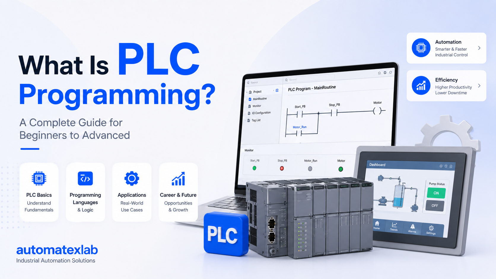
Industrial automation has transformed the way modern industries operate. Instead of relying completely on manual labor and traditional electrical control systems, factories now use intelligent automation systems to improve efficiency, accuracy, and productivity. One of the most important technologies behind this industrial transformation is the PLC, or Programmable Logic Controller.
PLCs are widely used in factories, manufacturing plants, and industrial facilities to automate machines and processes. From starting motors and controlling conveyor belts to operating robotic systems and monitoring water treatment plants, PLCs help industries run smoothly with minimal human intervention.
A PLC works like the “brain” of an automation system. It continuously receives signals from sensors and input devices, processes the information using programmed logic, and then controls outputs such as motors, valves, relays, alarms, and pumps. This allows machines to operate automatically, safely, and efficiently.
Unlike traditional relay-based systems, PLCs are highly flexible and can be easily programmed or modified according to industrial requirements. They are designed specifically for harsh industrial environments where reliability and fast response times are critical.
“From conveyor belts and motors to robotic systems and water treatment plants, PLCs control modern industrial operations automatically.”
In this complete guide, you will learn:
- The working principle of a PLC
- How PLC inputs and outputs function
- Understanding the PLC scan cycle
- Real industrial examples of PLC automation
- How PLCs control industrial machines and processes
By the end of this article, you will have a clear understanding of how PLC systems work and why they are essential in modern industrial automation.
Definition of PLC
PLC stands for Programmable Logic Controller.
A PLC is a specialized industrial computer designed to automate machines, manufacturing systems, and industrial processes. It monitors input signals from sensors and switches, processes the information based on programmed instructions, and controls output devices such as motors, relays, pumps, and valves.
Unlike normal computers, PLCs are built specifically for industrial environments where conditions can be harsh. They are capable of operating reliably in environments with:
- Dust
- Heat
- Moisture
- Vibrations
- Electrical noise
The primary purpose of a PLC is to automate repetitive industrial operations and reduce the need for manual control.
For example, in a manufacturing plant, a PLC can automatically:
- Start or stop conveyor belts
- Control machine operations
- Monitor temperature and pressure
- Operate filling and packaging machines
- Detect faults and trigger alarms
PLCs are programmable, meaning engineers can write custom logic according to the machine or process requirements. This flexibility makes PLCs one of the most important technologies in industrial automation.
Why PLCs Are Used in Industries
PLCs are widely used in industries because they provide reliable, fast, and efficient automation control. Before PLCs were introduced, industries mainly depended on relay-based control systems, which required extensive wiring and were difficult to modify or troubleshoot.
PLCs solved many of these problems and became the standard control system in industrial automation.
Automation
The biggest advantage of PLCs is automation. PLCs can automatically control machines and processes without constant human involvement. This improves operational efficiency and allows industries to run production systems continuously.
For example:
- Automatic conveyor systems
- Robotic assembly lines
- Automatic tank filling systems
Reliability
PLCs are designed for continuous industrial operation. They are highly reliable and can operate for long periods without failure, even in harsh factory environments.
Industrial plants depend on PLCs because machine downtime can lead to production losses and higher operational costs.
Fast Operation
PLCs process signals extremely quickly. They can read inputs, execute logic, and update outputs within milliseconds.
This fast response time is essential in applications like:
- Packaging systems
- High-speed manufacturing
- Safety systems
- Robotic automation
Reduced Manual Work
PLCs automate repetitive tasks that would otherwise require manual labor. This reduces operator workload and increases productivity.
Examples include:
- Automatic motor control
- Sensor-based machine operation
- Automated production systems
Better Safety
PLCs improve industrial safety by continuously monitoring machines and safety devices.
They can:
- Detect abnormal conditions
- Shut down equipment during faults
- Trigger alarms
- Prevent unsafe machine operation
Safety PLCs are commonly used in industries where worker and machine safety are critical.
Easy Troubleshooting
Modern PLC systems make troubleshooting easier through diagnostics and monitoring features.
Engineers can quickly identify:
- Faulty sensors
- Communication failures
- Program errors
- Output device problems
This reduces downtime and maintenance costs.
Industries That Use PLCs
PLCs are used in almost every major industry because automation is essential for modern production and process control.
Manufacturing Industry
Manufacturing plants use PLCs to automate production lines, machines, and assembly systems.
Applications include:
- Conveyor automation
- Robotic systems
- CNC machine control
- Assembly line automation
PLCs help manufacturers increase productivity and maintain consistent product quality.
Packaging Industry
Packaging systems rely heavily on PLC automation for high-speed operations.
PLC applications in packaging include:
- Bottle filling
- Labeling machines
- Carton packaging
- Sorting systems
PLCs ensure precise timing and synchronization in packaging operations.
Automotive Industry
The automotive sector uses PLCs extensively for automated manufacturing processes.
Applications include:
- Robotic welding
- Painting systems
- Engine assembly lines
- Material handling systems
PLCs help automotive plants achieve high production efficiency and accuracy.
Water Treatment Plants
Water treatment facilities use PLCs to monitor and control water systems automatically.
Applications include:
- Pump control
- Water level monitoring
- Chemical dosing systems
- Filtration control
PLCs help maintain stable and efficient water treatment operations.
Food Processing Industry
Food and beverage industries use PLCs to automate production and packaging while maintaining hygiene and consistency.
Applications include:
- Mixing systems
- Filling machines
- Temperature control
- Conveyor systems
Automation helps improve production speed and product quality.
Pharmaceutical Industry
Pharmaceutical companies use PLCs in highly controlled production environments.
Applications include:
- Batch processing
- Temperature monitoring
- Clean room automation
- Packaging systems
PLCs ensure accuracy and compliance with industrial standards.
Power Plants
Power generation facilities use PLCs for monitoring and controlling critical operations.
Applications include:
- Turbine control
- Boiler automation
- Alarm systems
- Generator monitoring
PLCs help maintain reliable and safe power generation processes.
Basic Working Principle of a PLC
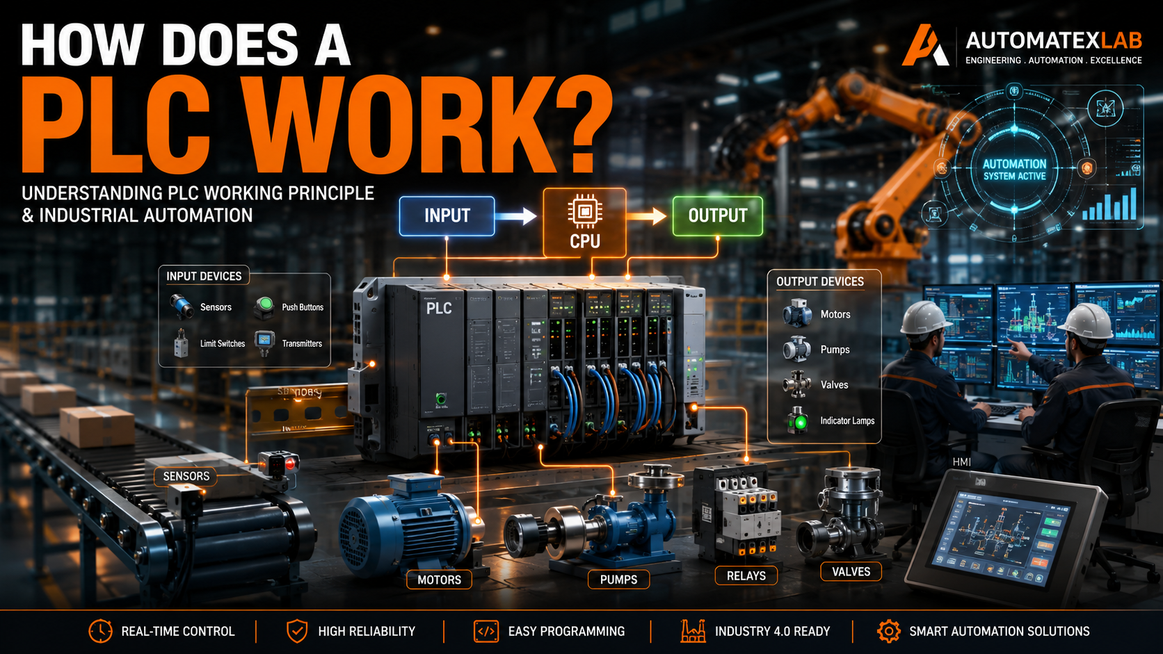
A PLC works by continuously monitoring industrial processes and controlling machines automatically based on programmed instructions. It acts like the control center of an automation system, receiving signals from input devices, processing the information, and controlling output devices accordingly.
The working principle of a PLC is simple but extremely powerful. It allows industries to automate repetitive and complex operations with high speed and accuracy.
Simple PLC Workflow
A PLC mainly works in three important steps:
- Receives Input Signals
- Processes Logic
- Controls Outputs
This entire process happens continuously within milliseconds, allowing machines to respond quickly in real time.
Simple PLC Workflow Diagram
Input Devices → PLC CPU → Output DevicesOr:
Sensors/Switches → Processing Logic → Motors/Valves/Relays1. Receives Input Signals
The PLC first receives signals from various input devices installed in the industrial system.
These devices provide information about machine conditions and process status.
Examples:
- Push button pressed
- Sensor detects object
- Temperature rises above limit
- Water tank becomes empty
The PLC continuously checks these input signals to understand what is happening in the system.
2. Processes Logic
After receiving inputs, the PLC CPU processes the information using the programmed logic stored in memory.
The program may contain:
- IF/THEN conditions
- Timers
- Counters
- Mathematical operations
- Safety interlocks
For example:
- IF sensor detects product → Start conveyor motor
- IF tank is full → Stop water pump
- IF emergency switch pressed → Shut down machine
The PLC makes decisions based on these programmed conditions.
3. Controls Outputs
Once the PLC processes the logic, it sends commands to output devices.
Outputs perform physical actions inside the machine or process.
Examples:
- Start motor
- Open valve
- Turn ON alarm
- Activate pump
- Stop conveyor
This automatic control allows industrial systems to operate efficiently without continuous manual intervention.
Real-Life Example of PLC Working
One of the easiest ways to understand PLC operation is through a conveyor automation system used in manufacturing plants.
Automatic Conveyor System Example
Imagine a factory where products move on a conveyor belt for packaging.
Step-by-Step Process
Step 1: Sensor Detects Product
A proximity sensor detects a product arriving at a certain position on the conveyor.
The sensor sends a signal to the PLC input module.
Step 2: PLC Receives Signal
The PLC CPU receives the sensor signal and checks the program logic.
The program may contain instructions such as:
- IF product detected → Start conveyor
- IF product reaches endpoint → Stop conveyor
Step 3: PLC Starts Conveyor Motor
Based on the program logic, the PLC activates the output connected to the conveyor motor.
The conveyor starts moving automatically.
Step 4: Conveyor Stops Automatically
Another sensor may detect when the product reaches the filling or packaging station.
The PLC then stops the conveyor motor automatically.
How Automation Reduces Human Effort
Without PLC automation:
- Workers would manually start and stop machines
- Human errors would increase
- Production speed would decrease
With PLC automation:
- Machines operate automatically
- Production becomes faster
- Accuracy improves
- Labor dependency reduces
- Industrial safety improves
This is why PLCs are considered the backbone of modern industrial automation systems.
Main Components Involved in PLC Working
A PLC system consists of multiple components that work together to automate industrial processes. Each component performs a specific function within the control system.
Understanding these components helps in learning how PLC systems operate in real industrial environments.
Input Devices
Input devices send signals and information to the PLC.
These devices monitor machine conditions, environmental parameters, and operator actions.
The PLC reads these signals and uses them to make decisions.
Common PLC Input Devices
Push Buttons
Used for:
- Start/stop operations
- Manual machine control
Proximity Sensors
Detect nearby objects without physical contact.
Applications:
- Conveyor systems
- Object detection
- Position sensing
Temperature Sensors
Measure temperature in industrial processes.
Applications:
- Boilers
- Ovens
- Food processing
- HVAC systems
Float Switches
Used for liquid level detection.
Applications:
- Water tanks
- Chemical tanks
- Pump control systems
Pressure Sensors
Monitor pressure levels in pipelines and machines.
Applications:
- Hydraulic systems
- Pneumatic systems
- Industrial process control
Limit Switches
Detect movement limits or machine positions.
Applications:
- CNC machines
- Conveyor systems
- Industrial equipment safety
Digital Inputs vs Analog Inputs
PLC inputs are generally divided into two types.
Digital Inputs
Digital inputs have only two states:
- ON
- OFF
Examples:
- Push buttons
- Limit switches
- Emergency switches
These signals are binary in nature.
Analog Inputs
Analog inputs provide continuously varying values.
Examples:
- Temperature sensors
- Pressure transmitters
- Flow meters
Analog signals help PLCs monitor real-time process values.
PLC CPU (Processor)
The CPU is the brain of the PLC system.
It controls all operations inside the PLC and processes the automation logic.
Main Functions of PLC CPU
- Reads input signals
- Executes programmed logic
- Makes decisions
- Updates outputs
- Monitors system status
The CPU continuously scans the entire system in cycles known as the PLC scan cycle.
This scan cycle happens extremely fast, often within milliseconds, allowing real-time machine control.
How CPU Continuously Scans the System
The PLC CPU repeatedly performs these operations:
- Reads all input signals
- Executes program logic
- Updates outputs
- Performs diagnostics
This cycle repeats continuously while the PLC is powered ON.
Because of this continuous scanning process, PLCs can respond quickly to changing industrial conditions.
Output Devices
Output devices perform actions based on commands sent by the PLC.
Once the PLC processes the logic, it activates outputs to control industrial equipment.
Common PLC Output Devices
Motors
Used for:
- Conveyor systems
- Pumps
- Fans
- Industrial machinery
Pumps
Applications:
- Water transfer
- Chemical dosing
- Fluid circulation
Relays
Used to switch electrical circuits ON or OFF.
Valves
Control fluid or gas flow in pipelines and process systems.
Buzzers
Provide audible alarms during:
- Fault conditions
- Warnings
- Emergency situations
Indicator Lamps
Used for machine status indication.
Examples:
- Machine running
- Fault detected
- System ready
Memory in PLC
PLC memory stores important operational data and programs.
PLC Memory Functions
Stores Program Logic
The ladder logic or control program is stored in memory.
Stores Input and Output Data
PLC stores the status of:
- Inputs
- Outputs
- Timers
- Counters
Retains Machine Logic
Some PLC memory types retain data even after power loss.
This helps maintain:
- Machine settings
- Process data
- Production parameters
Power Supply
The power supply provides the required operating voltage to the PLC system.
Without stable power, the PLC cannot function properly.
The power supply powers:
- CPU
- Input modules
- Output modules
- Communication modules
Industrial PLC systems typically operate on:
- 24V DC
- 120V AC
- 230V AC
depending on the application.
Communication Modules
Modern PLCs communicate with various industrial devices and software systems using communication modules.
These modules enable data exchange and centralized automation control.
PLC Communicates With:
HMI (Human Machine Interface)
HMIs allow operators to:
- Monitor machines
- View alarms
- Change settings
- Control processes
SCADA Systems
SCADA systems provide:
- Centralized monitoring
- Data logging
- Remote control
- Process visualization
VFDs (Variable Frequency Drives)
PLCs communicate with VFDs to:
- Control motor speed
- Improve energy efficiency
- Automate motor operations
Sensors
Modern smart sensors send advanced process data directly to PLC systems.
Industrial Networks
PLCs use industrial communication protocols such as:
- Modbus
- Profinet
- Profibus
- Ethernet/IP
These networks allow multiple automation devices to communicate efficiently within industrial environments.
Step-by-Step Explanation of How a PLC Works
A PLC works by continuously monitoring industrial inputs, processing programmed logic, and controlling outputs automatically. This entire process happens extremely fast and repeats continuously to ensure smooth industrial automation.
The operation of a PLC can be understood in four major steps.
Step 1 — PLC Reads Input Signals
The first step in PLC operation is reading input signals from connected devices.
The PLC continuously checks all input devices connected to the system to understand the current condition of the machine or process.
These input devices send electrical signals to the PLC whenever an event occurs.
Examples of Input Signals
- Start button pressed
- Sensor activated
- Temperature reaches threshold
- Emergency switch triggered
- Tank level becomes low
For example, when an operator presses the START push button, the button sends an electrical signal to the PLC input module.
Similarly:
- A proximity sensor may detect a product on a conveyor
- A temperature sensor may detect overheating
- A float switch may detect low water level
The PLC receives all these signals through its input modules.
How Input Modules Work
Input modules convert incoming electrical signals into readable digital data that the PLC CPU can process.
These modules act as the interface between field devices and the PLC processor.
For example:
- A 24V signal from a sensor is converted into a readable ON/OFF status
- Analog sensor values are converted into numerical data
The PLC constantly monitors these input conditions in real time.
Step 2 — PLC Executes Program Logic
After reading all input signals, the PLC CPU processes the control logic stored in memory.
This logic is programmed by automation engineers according to machine or process requirements.
The PLC CPU evaluates conditions and makes decisions based on the program instructions.
PLC Programming Languages Used
The logic inside the PLC can be written using different programming languages such as:
- Ladder Logic
- Function Block Diagram (FBD)
- Structured Text (ST)
Among these, ladder logic is the most widely used in industrial automation.
Examples of PLC Logic
The PLC follows programmed IF/THEN conditions.
Example 1
IF temperature > limit
THEN start cooling fan
In this case:
- PLC checks the temperature sensor
- If temperature exceeds the set value
- PLC activates the cooling fan
Example 2
IF sensor detects object
THEN stop conveyor
Here:
- Sensor sends detection signal
- PLC processes logic
- Conveyor motor stops automatically
How the CPU Makes Decisions
The CPU continuously:
- Reads input data
- Executes logic instructions
- Evaluates conditions
- Performs calculations
- Activates outputs accordingly
This decision-making capability is what makes PLCs highly effective for industrial automation.
Step 3 — PLC Updates Outputs
After processing the program logic, the PLC sends commands to output devices.
These outputs perform actual physical operations in the industrial system.
The PLC activates or deactivates outputs depending on the program conditions.
Examples of PLC Outputs
Start Motor
PLC energizes the motor starter to run machinery or conveyor systems.
Open Valve
PLC activates solenoid valves to control liquid or gas flow.
Turn ON Alarm
PLC activates buzzers or sirens during fault conditions.
Activate Pump
PLC starts pumps automatically when tank level becomes low.
Output Module Function
Output modules convert PLC commands into electrical signals capable of operating industrial equipment.
Outputs may control:
- Motors
- Relays
- Pumps
- Valves
- Indicator lamps
- Contactors
This automatic control enables industrial systems to operate efficiently with minimal human intervention.
Step 4 — PLC Repeats the Process
Once outputs are updated, the PLC immediately restarts the process from the beginning.
The PLC continuously repeats:
- Reading inputs
- Executing logic
- Updating outputs
This cycle occurs extremely fast, often within milliseconds.
Continuous Real-Time Operation
Because the PLC repeats this process continuously, it can respond instantly to changing industrial conditions.
For example:
- Sensors detect new products immediately
- Motors start or stop without delay
- Alarms activate instantly during faults
This continuous scanning process enables real-time automation and precise machine control.
Understanding the PLC Scan Cycle
The PLC scan cycle is the core operating process that allows PLCs to monitor and control industrial systems continuously.
Every PLC follows this repeated scan cycle while operating.
What Is a PLC Scan Cycle?
A PLC scan cycle is the repeated sequence of operations performed by the PLC to:
- Monitor inputs
- Process logic
- Control outputs
- Perform diagnostics
The PLC continuously performs these steps in a loop as long as power is supplied.
This scanning process happens very quickly, allowing real-time machine automation.
Stages of PLC Scan Cycle
The PLC scan cycle mainly consists of four stages.
Input Scan
During the input scan stage, the PLC reads all connected input signals.
The CPU checks:
- Push buttons
- Sensors
- Switches
- Analog devices
The PLC stores the current status of all inputs in memory.
For example:
- START button = ON
- Sensor = activated
- Temperature = 75°C
Program Scan
In this stage, the PLC executes the control program stored in memory.
The CPU processes:
- Ladder logic
- Timers
- Counters
- Arithmetic instructions
- Safety conditions
The PLC evaluates conditions and decides which outputs should be activated.
Output Scan
After processing the logic, the PLC updates all output devices.
The CPU sends signals to:
- Motors
- Relays
- Valves
- Pumps
- Alarm systems
Outputs operate according to the program conditions.
Housekeeping
In the housekeeping stage, the PLC performs internal operations such as:
- Communication updates
- Diagnostics
- Memory management
- Error checking
This ensures stable and reliable PLC operation.
Why Scan Time Matters
Scan time refers to how quickly the PLC completes one full scan cycle.
A faster scan time improves system performance significantly.
Better Response
Fast scan times allow PLCs to respond quickly to input changes.
This is important in:
- High-speed packaging systems
- Robotics
- Conveyor automation
Higher Efficiency
Faster processing improves machine productivity and reduces delays.
Improved Automation Accuracy
Quick scan cycles ensure precise machine operation and synchronization.
This is especially important in:
- Filling machines
- CNC systems
- Motion control applications
Types of Inputs and Outputs in PLC Systems
PLCs use different types of inputs and outputs depending on the application requirements.
These are generally divided into digital and analog types.
Digital Inputs
Digital inputs have only two states:
- ON
- OFF
These signals are binary in nature.
Examples of Digital Inputs
- ON/OFF switches
- Push buttons
- Limit switches
- Emergency stop buttons
Digital inputs are commonly used for basic machine control operations.
Analog Inputs
Analog inputs provide continuously varying signal values instead of simple ON/OFF states.
These signals represent real-world measurements.
Examples of Analog Inputs
- Temperature transmitters
- Pressure sensors
- Flow sensors
- Level transmitters
Continuous Value Signals
Analog devices send continuously changing values such as:
- 0–10V
- 4–20mA
The PLC converts these signals into numerical values for processing.
This allows accurate process monitoring and control.
Digital Outputs
Digital outputs operate devices in ON/OFF mode.
Examples of Digital Outputs
- Relays
- Contactors
- Solenoid valves
- Indicator lamps
Digital outputs are widely used for motor starters and machine control.
Analog Outputs
Analog outputs provide variable signals for precise control applications.
Examples of Analog Outputs
VFD Speed Control
PLC controls motor speed by sending analog signals to Variable Frequency Drives.
Valve Positioning
PLC controls valve opening percentage for flow regulation.
Analog outputs enable smooth and accurate process control.
Example of PLC Working in Real Industries
PLCs are used across multiple industries to automate machines and improve operational efficiency.
PLC in Conveyor Automation
Conveyor systems are one of the most common PLC applications in industries.
PLC Functions in Conveyor Systems
Product Detection
Sensors detect products moving on the conveyor.
Motor Start/Stop
PLC automatically controls conveyor motors.
Sorting Automation
PLC sorts products based on size, color, or position using sensors and actuators.
This improves speed and reduces manual handling.
PLC in Water Treatment Plant
Water treatment facilities use PLCs for automatic monitoring and process control.
PLC Applications
Tank Level Monitoring
PLC monitors water levels using float switches or level sensors.
Automatic Pump Control
PLC automatically starts or stops pumps depending on tank conditions.
Alarm Systems
PLC activates alarms during:
- Overflow conditions
- Low water levels
- Pump failures
This ensures efficient and safe water management.
PLC in Packaging Industry
Packaging industries rely heavily on PLC automation for high-speed production.
PLC Applications
Filling Machines
PLC controls accurate filling operations.
Bottle Counting
Sensors and PLCs count bottles automatically.
Labeling Automation
PLC synchronizes labeling systems with conveyor movement.
Automation increases packaging speed and consistency.
PLC in Manufacturing Plants
Modern manufacturing plants use PLCs extensively for automation.
PLC Applications
Robotic Systems
PLCs control robotic arms and automated machines.
CNC Machines
PLC manages machine operations and safety systems.
Assembly Lines
PLC coordinates production line activities and machine synchronization.
This helps industries achieve:
- Higher productivity
- Better quality control
- Reduced downtime
- Improved operational efficiency
How PLC Makes Decisions
One of the most important functions of a PLC is decision-making. A PLC continuously analyzes input conditions and performs actions based on the programmed instructions stored inside its memory.
Unlike traditional electrical systems that rely only on physical wiring, PLCs use programmable logic to make intelligent automation decisions in real time.
This allows industries to automate complex operations accurately and efficiently.
Logic-Based Operations
PLCs follow logic-based instructions written by automation engineers. These instructions define how machines should behave under different operating conditions.
The PLC continuously checks inputs, evaluates conditions, and decides whether outputs should be activated or deactivated.
IF/THEN Logic
The most common type of PLC logic is IF/THEN logic.
Examples:
- IF start button is pressed THEN start motor
- IF temperature exceeds limit THEN turn ON cooling fan
- IF tank becomes full THEN stop pump
This logic enables machines to operate automatically without human intervention.
Timers
Timers are used when actions need to happen after a specific delay.
Examples:
- Delay motor startup
- Turn OFF alarm after 10 seconds
- Start conveyor after system initialization
Timers help synchronize industrial operations accurately.
Counters
Counters are used to count events or objects in industrial processes.
Examples:
- Count bottles on conveyor
- Count machine cycles
- Count production quantity
Counters help industries monitor productivity and automate quantity-based operations.
Interlocks
Interlocks are safety conditions programmed inside PLC systems.
They prevent machines from operating under unsafe conditions.
Examples:
- Conveyor cannot start unless safety guard is closed
- Pump cannot run if water level is low
- Machine stops during emergency conditions
Interlocks are essential for industrial safety and equipment protection.
Timers in PLC
Timers are special PLC instructions used for delayed operations.
Instead of activating outputs instantly, timers allow the PLC to wait for a predefined time before performing an action.
Timers are widely used in industrial automation systems where process sequencing and timing are important.
Example of PLC Timer
Start motor after 5 seconds.
Working process:
- Operator presses START button
- PLC activates timer
- Timer counts 5 seconds
- PLC starts motor automatically
Timers help:
- Prevent sudden machine operation
- Synchronize industrial systems
- Improve process accuracy
Counters in PLC
Counters are used to count repeated events, products, or machine operations.
The PLC increases or decreases the count value whenever a specific event occurs.
Counters are commonly used in:
- Packaging industries
- Conveyor systems
- Production lines
- Batch processing
Example of PLC Counter
Bottle counting system:
- Sensor detects each bottle
- PLC counter increases count by 1
- When count reaches target value
- Conveyor stops automatically
Counters improve automation accuracy and production monitoring.
Safety Interlocks
Safety interlocks are programmed conditions that prevent dangerous machine operations.
Industrial machines can be hazardous if operated incorrectly. PLC safety interlocks ensure machines run only when safe operating conditions are met.
Example of Safety Interlock
Motor cannot start unless safety door is closed.
Working process:
- PLC checks safety door sensor
- If door is open → motor remains OFF
- If door is closed → motor can start
Safety interlocks help:
- Protect workers
- Prevent machine damage
- Improve operational safety
- Meet industrial safety standards
Modern industries heavily rely on PLC-based safety systems for reliable automation.
PLC Programming Languages Used in Automation
PLCs can be programmed using different programming languages depending on the application complexity and industrial requirements.
These programming languages are standardized under IEC 61131-3, the international standard for PLC programming.
Different languages are suitable for different types of automation systems.
Ladder Logic
Ladder Logic is the most widely used PLC programming language in industrial automation.
It looks similar to traditional electrical relay diagrams, making it easy for electricians and automation engineers to understand.
Ladder logic uses:
- Contacts
- Coils
- Rungs
- Timers
- Counters
It is commonly used for:
- Motor control
- Conveyor systems
- Industrial machine automation
- Safety systems
Why Ladder Logic Is Most Common
Ladder logic became popular because:
- Easy to learn
- Simple troubleshooting
- Similar to electrical wiring diagrams
- Highly reliable
- Ideal for industrial control systems
Even today, ladder logic remains the industry standard for PLC programming.
Function Block Diagram (FBD)
Function Block Diagram is a graphical programming language that uses interconnected blocks to represent functions.
Each block performs a specific operation such as:
- Timers
- Counters
- Mathematical calculations
- Signal processing
FBD is commonly used in:
- Process industries
- Analog control systems
- Complex automation processes
Structured Text (ST)
Structured Text is a high-level text-based PLC programming language similar to traditional computer programming languages.
It is useful for:
- Complex calculations
- Data processing
- Advanced automation logic
Structured Text is commonly used in modern automation systems requiring advanced programming capabilities.
Sequential Function Chart (SFC)
Sequential Function Chart is used for step-by-step process automation.
It helps engineers design automation sequences visually.
SFC is commonly used in:
- Batch processing
- Sequential machine operations
- Manufacturing systems
This language is ideal for automation systems with multiple operating stages.
PLC Communication with Other Systems
Modern PLCs do much more than simple machine control. They communicate with multiple industrial devices and software systems to create fully integrated automation environments.
Communication capabilities allow PLCs to exchange data, monitor operations, and control industrial systems efficiently.
PLC and HMI Communication
HMI stands for Human Machine Interface.
An HMI allows operators to interact with machines and monitor industrial processes visually.
PLCs communicate with HMIs to provide:
- Machine status
- Alarm notifications
- Process values
- System controls
- Production data
Operators can use HMIs to:
- Start or stop machines
- Adjust settings
- Monitor faults
- View automation data
This improves operator control and system visibility.
PLC and SCADA Integration
SCADA stands for Supervisory Control and Data Acquisition.
SCADA systems provide centralized monitoring and control for large industrial operations.
PLCs send real-time data to SCADA systems for:
- Process monitoring
- Data logging
- Alarm management
- Remote operation
- Production analysis
SCADA systems are commonly used in:
- Power plants
- Water treatment facilities
- Manufacturing plants
- Oil & gas industries
PLC-SCADA integration enables industries to manage entire plants from centralized control rooms.
Industrial Communication Protocols
PLCs use industrial communication protocols to exchange data with automation devices.
These protocols allow reliable communication between:
- PLCs
- HMIs
- SCADA systems
- VFDs
- Sensors
- Industrial networks
Modbus
Modbus is one of the oldest and most widely used industrial communication protocols.
It is simple, reliable, and commonly used for:
- PLC communication
- Industrial devices
- Remote monitoring systems
Profibus
Profibus is a high-speed industrial network commonly used in manufacturing automation.
It supports communication between:
- PLCs
- Sensors
- Drives
- Industrial controllers
Profinet
Profinet is an industrial Ethernet-based communication protocol.
It provides:
- Fast data transfer
- Real-time communication
- Advanced industrial networking
Widely used in Siemens automation systems.
Ethernet/IP
Ethernet/IP is a modern industrial Ethernet protocol used in advanced automation systems.
It enables:
- High-speed industrial communication
- Device integration
- Real-time data exchange
Commonly used with Allen-Bradley PLC systems.
Advantages of PLC-Based Automation
PLC-based automation offers many advantages compared to traditional control systems.
This is why PLCs are used in almost every modern industrial facility.
High Reliability
PLCs are designed for harsh industrial environments.
They can operate reliably under:
- Dust
- Heat
- Vibrations
- Electrical noise
This reliability minimizes production downtime.
Faster Automation
PLCs process data extremely quickly.
Fast response times improve:
- Machine performance
- Production speed
- Automation efficiency
Reduced Human Error
Automation reduces dependency on manual operations.
This minimizes:
- Operational mistakes
- Production errors
- Inconsistent machine control
Easy Troubleshooting
Modern PLC systems provide diagnostics and fault monitoring.
Engineers can quickly identify:
- Faulty sensors
- Program errors
- Communication failures
This reduces maintenance time significantly.
Flexible Programming
PLC programs can be modified easily without changing physical wiring.
This allows industries to:
- Upgrade machines
- Add new functions
- Improve automation systems
without major hardware modifications.
Lower Maintenance
Compared to relay-based systems, PLCs require less maintenance because they contain fewer mechanical components.
This reduces:
- Repair costs
- Downtime
- Maintenance effort
Better Industrial Safety
PLCs support:
- Safety interlocks
- Emergency shutdown systems
- Alarm monitoring
This improves worker safety and machine protection.
PLC vs Traditional Relay Logic
Before PLCs were introduced, industries mainly used relay-based control systems for automation.
However, relay systems had many limitations such as:
- Complex wiring
- Difficult troubleshooting
- Large control panels
- Poor flexibility
PLCs replaced relay logic because they provide faster, more reliable, and more flexible automation.
PLC vs Relay Logic Comparison Table
| Feature | PLC | Relay Logic |
|---|---|---|
| Wiring | Less | More |
| Flexibility | High | Low |
| Maintenance | Easy | Difficult |
| Space | Compact | Large |
| Troubleshooting | Fast | Slow |
Why PLCs Replaced Relay Systems
Traditional relay systems required extensive wiring and physical modifications whenever changes were needed.
As industrial systems became more complex, relay logic became difficult to maintain and troubleshoot.
PLCs solved these problems by introducing programmable automation.
Advantages of PLCs over relay systems include:
- Easier programming changes
- Reduced panel wiring
- Faster troubleshooting
- Compact control systems
- Better scalability
- Improved reliability
Today, PLCs are the standard control technology used in modern industrial automation systems worldwide.
Common PLC Applications
PLCs are used in a wide range of industrial and commercial applications because of their reliability, flexibility, and ability to automate complex operations. From small machine control systems to large industrial plants, PLCs play a critical role in modern automation.
Below are some of the most common applications of PLC systems in industries.
Motor Control
Motor control is one of the most common PLC applications in industrial automation.
PLCs are used to:
- Start and stop motors
- Reverse motor direction
- Control motor sequences
- Protect motors from overload conditions
- Control motor speed using VFDs
Industries use PLC-based motor control systems in:
- Conveyor systems
- Pumps
- Compressors
- Fans
- Industrial machinery
For example, in a conveyor system, the PLC automatically starts the conveyor motor when a product is detected and stops it when the operation is completed.
PLC-based motor control improves:
- Operational efficiency
- Safety
- Energy management
- Automation accuracy
Process Automation
PLCs are widely used in process industries to automate continuous industrial operations.
Process automation involves monitoring and controlling variables such as:
- Temperature
- Pressure
- Flow
- Level
- Speed
Industries that rely heavily on process automation include:
- Water treatment plants
- Chemical industries
- Pharmaceutical manufacturing
- Food processing plants
- Oil & gas industries
For example:
- PLC automatically controls water pumps based on tank levels
- PLC maintains temperature in industrial boilers
- PLC controls chemical dosing systems
Process automation improves consistency, accuracy, and production efficiency.
Industrial Robotics
Modern industrial robots heavily depend on PLC systems for control and coordination.
PLCs help control:
- Robotic arm movement
- Positioning systems
- Production synchronization
- Safety interlocks
Industrial robots are commonly used in:
- Automotive manufacturing
- Welding systems
- Material handling
- Packaging operations
- Assembly lines
PLCs ensure robots operate safely and accurately within automated production systems.
Traffic Control Systems
PLCs are commonly used in automated traffic control systems.
Applications include:
- Traffic signal control
- Railway crossing automation
- Parking systems
- Toll gate automation
For example:
- PLC changes traffic light sequences automatically
- Sensors detect vehicle movement
- PLC controls signal timing efficiently
PLC automation improves traffic management and road safety.
Elevator Automation
Elevator systems use PLCs to control movement, safety, and door operations.
PLCs manage:
- Floor selection
- Motor control
- Door opening/closing
- Emergency systems
- Safety interlocks
Modern elevators use PLC-based systems for smooth and reliable operation.
PLC automation improves:
- Passenger safety
- Operational reliability
- Elevator efficiency
HVAC Systems
HVAC stands for Heating, Ventilation, and Air Conditioning.
PLCs are widely used in HVAC automation systems for:
- Temperature control
- Fan operation
- Airflow management
- Humidity control
- Energy optimization
Applications include:
- Commercial buildings
- Factories
- Hospitals
- Data centers
PLC-based HVAC systems improve energy efficiency and environmental control.
Common Problems in PLC Systems
Although PLC systems are highly reliable, industrial environments can still cause operational problems. Identifying and troubleshooting PLC issues quickly is important to reduce downtime and maintain productivity.
Below are some common PLC problems and their solutions.
Input Signal Failure
Input signal failures occur when the PLC does not receive proper signals from sensors or switches.
Possible causes:
- Damaged sensors
- Loose wiring
- Faulty input modules
- Electrical noise
- Incorrect voltage
Symptoms:
- Machine not starting
- Sensors not responding
- Incorrect automation sequence
Basic Troubleshooting Tips
- Check sensor power supply
- Inspect wiring connections
- Verify input status LEDs
- Test sensor functionality
- Replace faulty input devices if needed
Faulty Outputs
Output problems occur when PLC outputs fail to control devices properly.
Possible causes:
- Damaged relay or contactor
- Burnt output module
- Wiring faults
- Overloaded outputs
Symptoms:
- Motor not starting
- Valve not opening
- Alarm not activating
Basic Troubleshooting Tips
- Check output module indicators
- Verify output voltage
- Inspect relays and contactors
- Test field devices manually
- Replace faulty output modules
Communication Errors
Modern PLC systems communicate with HMIs, SCADA systems, VFDs, and industrial networks. Communication failures can interrupt automation processes.
Possible causes:
- Incorrect communication settings
- Damaged communication cables
- Protocol mismatch
- Network failure
Symptoms:
- HMI not responding
- SCADA data loss
- Communication timeout alarms
Basic Troubleshooting Tips
- Verify communication settings
- Check IP addresses and baud rates
- Inspect network cables
- Restart communication devices
- Confirm protocol compatibility
Power Supply Issues
PLC systems require stable power for reliable operation.
Power-related issues can cause:
- PLC shutdown
- Unexpected restarts
- Program corruption
Possible causes:
- Voltage fluctuations
- Power supply failure
- Loose terminals
- Overheating
Basic Troubleshooting Tips
- Check input voltage
- Inspect power supply module
- Tighten electrical connections
- Use surge protection devices
- Monitor overheating conditions
Program Errors
Programming mistakes can cause machines to behave incorrectly.
Examples:
- Wrong timer settings
- Incorrect logic conditions
- Addressing errors
- Faulty interlocks
Symptoms:
- Unexpected machine behavior
- Incorrect sequence operation
- Automation failure
Basic Troubleshooting Tips
- Review ladder logic carefully
- Monitor PLC status online
- Check timer and counter values
- Simulate logic before implementation
- Use proper program documentation
Future of PLC Automation
Industrial automation is evolving rapidly with advancements in digital technologies and smart manufacturing systems. Modern PLCs are becoming more intelligent, connected, and capable of handling advanced automation applications.
The future of PLC automation is closely linked with Industry 4.0 and smart factory technologies.
Industry 4.0
Industry 4.0 refers to the next generation of industrial automation where machines, devices, and systems are interconnected digitally.
PLCs play a major role in Industry 4.0 by enabling:
- Smart automation
- Real-time data exchange
- Advanced process monitoring
- Automated decision-making
Modern PLCs support:
- Ethernet communication
- Data analytics
- Remote monitoring
- Industrial IoT integration
Industry 4.0 helps industries improve productivity, efficiency, and operational visibility.
Smart Factories
Smart factories use connected automation systems to create highly efficient production environments.
PLCs are the backbone of smart factories because they:
- Collect machine data
- Control automated systems
- Communicate with industrial networks
- Support centralized monitoring
Smart factories help industries achieve:
- Higher production efficiency
- Reduced downtime
- Better quality control
- Predictive maintenance
IIoT Integration
IIoT stands for Industrial Internet of Things.
Modern PLCs can connect with cloud platforms and industrial devices through IIoT technologies.
IIoT integration allows:
- Real-time machine monitoring
- Remote diagnostics
- Data analytics
- Predictive maintenance
- Smart production systems
Industries can monitor automation systems remotely from anywhere using internet-connected PLC solutions.
Cloud-Based Monitoring
Cloud-based automation systems allow industries to monitor and control operations remotely.
PLCs can send real-time data to cloud servers for:
- Production monitoring
- Performance analysis
- Alarm notifications
- Maintenance tracking
Benefits include:
- Remote accessibility
- Improved decision-making
- Better operational visibility
- Centralized data storage
Cloud-based monitoring is becoming increasingly important in modern industrial automation.
AI-Based Automation
Artificial Intelligence (AI) is gradually being integrated into industrial automation systems.
AI-based PLC automation can:
- Predict machine failures
- Optimize production processes
- Improve energy efficiency
- Analyze industrial data automatically
Future PLC systems may combine:
- AI
- Machine learning
- Smart sensors
- Advanced robotics
This will lead to more intelligent and autonomous industrial systems.
Why Choose AutomatexLab for PLC Automation Solutions
AutomatexLab provides advanced industrial automation solutions designed to improve productivity, reliability, and operational efficiency for modern industries.
Our team delivers customized automation systems tailored to industrial requirements across multiple sectors.
Our PLC Automation Services
PLC Programming
Custom PLC programming solutions for industrial machines and automated systems.
SCADA Development
Advanced SCADA systems for centralized monitoring, control, and data visualization.
HMI Design
User-friendly HMI interfaces for machine operation and real-time monitoring.
Industrial Automation
Complete industrial automation solutions for manufacturing plants and industrial facilities.
Control Panel Solutions
Design and development of reliable electrical and PLC control panels.
PLC Troubleshooting
Fast diagnosis and troubleshooting for PLC systems, communication issues, and automation failures.
Machine Automation
Automation solutions for:
- Conveyor systems
- Packaging machines
- Industrial machinery
- Process control systems
Why Industries Choose AutomatexLab
- Experienced automation engineers
- Reliable industrial solutions
- Customized PLC programming
- Fast technical support
- Modern automation technologies
- Scalable automation systems
“AutomatexLab helps industries automate operations with reliable PLC programming and industrial automation solutions.”
Conclusion
PLCs have become the foundation of modern industrial automation systems. From simple machine control to advanced industrial processes, PLCs help industries achieve faster, safer, and more efficient operations.
In this guide, we explored the complete working principle of a PLC and understood how it continuously:
- Reads input signals
- Processes programmed logic
- Controls output devices
- Performs real-time automation
We also covered important concepts such as:
- PLC scan cycle
- Input and output systems
- PLC programming languages
- Communication protocols
- Industrial applications
- Automation advantages
One of the biggest strengths of PLC systems is their ability to provide real-time control. PLCs can monitor industrial conditions instantly and respond within milliseconds, making them ideal for high-speed automation environments such as manufacturing plants, packaging systems, robotic applications, and process industries.
As industries move toward Industry 4.0, smart factories, IIoT integration, and AI-driven automation, PLC technology will continue to play a major role in future industrial systems. Modern PLCs are becoming more connected, intelligent, and capable of handling advanced automation requirements.
Whether it is machine automation, process control, SCADA integration, or smart manufacturing, PLCs remain one of the most reliable and essential technologies in industrial automation.
FAQs
The working principle of a PLC is based on three main steps:
Reading input signals from sensors and switches
Processing logic through the CPU
Controlling output devices such as motors, relays, and valves
The PLC continuously repeats this process in a scan cycle, allowing real-time industrial automation and machine control.
A PLC controls machines by receiving signals from input devices, processing programmed instructions, and sending commands to output devices.
For example:
A sensor detects a product
PLC processes the signal
PLC starts or stops a motor automatically
This allows machines to operate automatically without manual intervention.
Inputs are devices that send signals to the PLC, while outputs are devices controlled by the PLC.
Examples of PLC Inputs
Push buttons
Sensors
Switches
Temperature transmitters
Examples of PLC Outputs
Motors
Pumps
Relays
Valves
Alarm systems
Inputs provide information to the PLC, and outputs perform physical actions based on the PLC program.
The PLC scan cycle is the continuous process followed by the PLC to monitor and control industrial systems.
The scan cycle includes:
Input scan
Program execution
Output update
Housekeeping operations
This cycle repeats continuously within milliseconds for real-time automation.
PLCs are used in automation because they provide:
Fast machine control
High reliability
Flexible programming
Reduced human error
Easy troubleshooting
Better industrial safety
They help industries automate repetitive and complex operations efficiently.
PLCs are widely used in many industries, including:
Manufacturing
Packaging
Automotive
Water treatment
Food processing
Pharmaceutical
Oil & gas
Power plants
Almost every modern industrial facility uses PLC-based automation systems.
PLCs operate extremely fast. Most PLCs complete one scan cycle within milliseconds.
The actual speed depends on:
PLC processor performance
Program size
Number of inputs and outputs
Communication load
Fast scan times allow PLCs to perform real-time industrial automation accurately.
PLCs can be programmed using several programming languages, including:
Ladder Logic
Function Block Diagram (FBD)
Structured Text (ST)
Sequential Function Chart (SFC)
Among these, ladder logic is the most commonly used PLC programming language in industrial automation.
Yes, a PLC can work without sensors in simple manual control applications using push buttons and switches.
However, in most industrial automation systems, sensors are essential because they provide real-time information about machine conditions and processes.
Without sensors, the PLC cannot monitor:
Position
Temperature
Pressure
Level
Motion
Object detection
Sensors make PLC automation more intelligent, accurate, and efficient.