Configuring PLC hardware correctly is the foundation of every reliable automation system. Before a single line of ladder logic gets written, the PLC needs to know exactly what hardware it is talking to. Skip this step or get it wrong, and you end up with communication faults, addressing conflicts, and a system that behaves unpredictably once it hits the plant floor.
This guide walks through the entire PLC hardware configuration process from start to finish. Whether you are a student learning automation for the first time, a maintenance technician troubleshooting an existing panel, or an engineer commissioning a new machine, this is the reference you need.
What Is PLC Hardware Configuration?
PLC hardware configuration is the process of telling the PLC’s engineering software exactly which physical components are installed in the system. That includes the CPU, power supply, input and output modules, communication modules, and any expansion racks.
Hardware configuration is not the same thing as programming. Programming is the logic that tells the machine what to do. Hardware configuration is what makes that logic possible in the first place, because the CPU cannot execute instructions for I/O points it does not know exist.
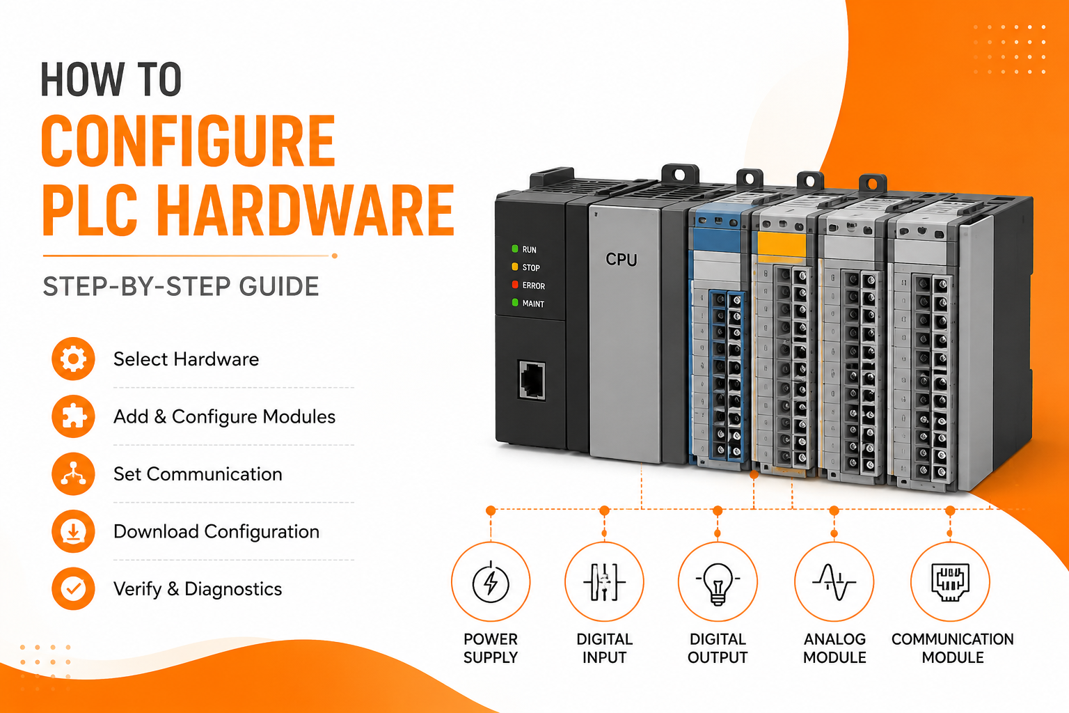
Every PLC project, regardless of brand or platform, starts with hardware configuration. This includes:
CPU
The processor that runs the control program and manages communication with all connected modules.
Power supply
Provides voltage to the rack and all installed modules.
Digital inputs
Read on/off signals from sensors, switches, and pushbuttons.
Digital outputs
Send on/off signals to relays, solenoids, and indicator lights.
Analog modules
Handle continuous signals like 4-20 mA or 0-10 V for pressure, temperature, and flow measurement.
Communication modules
Handle networking protocols such as Ethernet, Profinet, Profibus, and Modbus.
Expansion modules
Add extra I/O capacity when the base rack runs out of slots.
Why Does Hardware Configuration Matter?
Hardware configuration matters because it is the bridge between the physical panel and the software running inside the CPU. Without it, the PLC has no way to recognize which modules are installed, what addresses they occupy, or how to communicate with connected devices.
Getting this right up front saves hours of troubleshooting later. Here is what proper configuration accomplishes.
It lets the PLC recognize installed hardware
The CPU compares the configured hardware against what is physically installed. If they do not match, most platforms will flag a module fault immediately.
It eliminates addressing conflicts
Every input and output needs a unique address. Manual or automatic addressing done correctly prevents two devices from fighting over the same memory location.
It enables proper communication
Network modules need IP addresses, node numbers, and device names configured before they can talk to HMIs, SCADA systems, or other PLCs.
It prevents runtime faults
A large percentage of PLC faults during startup trace back to configuration mismatches rather than programming errors.
It speeds up troubleshooting
When hardware is documented and configured cleanly, diagnosing a fault takes minutes instead of hours.
It supports scalability
A well-configured system is far easier to expand later, whether that means adding I/O, integrating a new HMI, or connecting to a plant-wide SCADA network.
What Hardware Do You Need Before Configuration?
Before opening any engineering software, gather the following information and hardware. Having this ready prevents delays once you start building the project.
What CPU should you select?
The CPU is the brain of the system. When selecting or confirming a CPU, check:
- Processor family and exact part number
- Firmware version currently installed
- Memory capacity relative to program size and data storage needs
Mismatched firmware between the physical CPU and the project file is one of the most common reasons a configuration fails to download.
What are the power supply requirements?
The power supply needs to match the voltage requirements of the rack and provide enough current capacity for every module installed, including any future expansion. Undersized power supplies are a common cause of intermittent module faults.
What input modules will you need?
Digital inputs read discrete signals from field devices like limit switches and pushbuttons. Analog inputs read continuous values from sensors like pressure transmitters and thermocouples. Know your input count and signal types before configuring.
What output modules will you need?
Digital outputs drive discrete devices such as solenoids, relays, and pilot lights. Analog outputs typically control variable speed drives or proportional valves. Match module type to the load being controlled.
Which communication protocol fits your system?
Common industrial communication options include:
- Ethernet
- Profinet
- Profibus
- Modbus TCP
- Modbus RTU
- EtherNet/IP
The right choice depends on the PLC brand, existing plant infrastructure, and what other devices need to communicate with the system.
Which engineering software will you use?
Configuration happens inside the manufacturer’s software platform. Common options include:
- TIA Portal (Siemens)
- Studio 5000 (Allen-Bradley)
- GX Works (Mitsubishi)
- CX Programmer (Omron)
- EcoStruxure Machine Expert (Schneider Electric)
How Do You Create a New PLC Project?
Start by opening your engineering software and creating a new project. This step establishes the foundation everything else builds on.
- Select the PLC family that matches your hardware
- Choose the exact CPU model installed in the panel
- Select the firmware version that matches the physical CPU
- Save the project with a clear, descriptive name
A quick tip here: name projects using the machine or line number, not just the client name. It makes version control and future troubleshooting much faster.
How Do You Add the PLC CPU to the Project?
Once the project is created, browse the hardware catalog inside the software and select the exact CPU model. Insert it into the project at the correct rack position.
Pay close attention to slot numbering. Most platforms number slots starting from either 0 or 1 depending on the manufacturer, and the CPU typically occupies a fixed position relative to the power supply. Getting slot numbering wrong here cascades into every module added afterward.
How Do You Configure the Power Supply?
Configure the power supply by matching it to the physical rack layout and confirming the supply voltage matches what is installed. If the system uses expansion racks, verify that the power supply and rack are rated for the additional current draw from those modules.
How Do You Add Digital Input Modules?
Select the digital input module from the hardware catalog and assign it to the correct slot. The software will typically auto-assign addresses, but you should verify them.
A typical digital input address sequence looks like this:
- I0.0
- I0.1
- I0.2
Confirm each address lines up with the physical wiring diagram before moving forward.
How Do You Configure Digital Output Modules?
Digital output modules follow the same process as inputs. Assign the module to its slot and confirm the output addressing.
A typical digital output address sequence looks like this:
- Q0.0
- Q0.1
- Q0.2
Double check output addresses against the wiring schematic, especially on panels with multiple output cards.
How Do You Configure Analog Modules?
Analog modules require more setup than digital ones because they involve signal type, scaling, and resolution.
Key settings to configure include:
Signal type
Voltage inputs (0-10 V), current inputs (4-20 mA), RTD, or thermocouple.
Scaling
Converting the raw signal into an engineering unit the program can use, such as PSI, degrees, or GPM.
Resolution
The bit depth of the analog channel, which determines measurement precision.
Sensor type
RTDs and thermocouples require specific settings that match the sensor curve being used.
Getting scaling wrong is one of the most common analog configuration mistakes. Always verify scaled values against a known reference before trusting the readings in production.
How Do You Configure Communication Modules?
Communication modules need protocol-specific settings entered before the PLC can talk to other devices on the network.
For Ethernet-based protocols like Profinet and Modbus TCP, you will typically configure:
- IP address
- Device name
- Node address (where applicable)
For serial protocols like Modbus RTU, you will configure:
- Baud rate
- Node address
- Parity and stop bits
Every device on the network needs a unique address. Duplicate IP addresses or node numbers are one of the most frequent causes of communication failures during commissioning.
How Do You Configure Network Settings?
Network configuration ties the PLC into the broader plant network. Settings typically include:
- Static IP address
- Subnet mask
- Gateway address
- Device name
- PLC identification within the project
- Overall network topology
Using a static IP rather than DHCP is standard practice for PLCs, since an address change can break communication with HMIs and SCADA systems without warning.
How Do You Configure I/O Address Mapping?
Address mapping can be automatic or manual depending on the platform. Automatic addressing is faster and works well for straightforward systems. Manual addressing gives more control and is often preferred on larger systems where specific address ranges need to stay consistent across program revisions.
A simple I/O address mapping table looks like this:
| Module | Address Range |
|---|---|
| Digital Input | I0.0 to I1.7 |
| Digital Output | Q0.0 to Q1.7 |
| Analog Input | IW64 |
| Analog Output | QW64 |
Documenting this table separately from the project file makes it much easier for other technicians to understand the system later.
How Do You Configure Module Parameters?
Beyond basic addressing, most modules allow parameter-level configuration, including:
- Input filtering, which reduces false triggers from electrical noise
- Output behavior on CPU stop or fault
- Startup values for outputs
- Watchdog timer settings
- Diagnostic reporting
- Interrupt settings for time-critical inputs
These parameters are easy to skip but often make the difference between a system that runs reliably and one that faults unexpectedly during normal operation.
How Do You Compile the Hardware Configuration?
Once every module is added and addressed, compile the hardware configuration inside the software. Compiling checks the configuration for errors before it gets downloaded to the physical CPU.
Common compile errors include:
- Duplicate addresses assigned to more than one module
- A firmware mismatch between the project and physical CPU
- Modules configured in the project but missing from the physical rack
- An invalid or unsupported slot assignment
Fix every compile error before attempting to download. A configuration that compiles clean is far less likely to cause problems in the field.
How Do You Download the Configuration to the PLC?
Downloading pushes the compiled hardware configuration from the software to the physical CPU. Most platforms support Ethernet, USB, or serial download methods.
Before downloading, confirm the following:
- The PLC is in STOP mode
- The correct IP address or communication path is selected
- The engineering software shows an active online connection to the CPU
Downloading configuration changes to a running machine can cause outputs to change state unexpectedly, so always confirm the machine is in a safe state first.
How Do You Verify Hardware Diagnostics After Download?
After downloading, verify that every module is healthy and communicating correctly. Check the following:
- Module status indicators in the engineering software
- Communication status for every networked device
- Physical LED indicators on each module
- Online diagnostics within the software
- The CPU fault buffer for any logged errors
A system that downloads successfully but shows diagnostic warnings is not ready for production. Clear every warning before handing the system over.
Example: Configuring a Bottle Filling Machine
Here is a practical example that ties the whole process together.
A bottle filling machine typically requires:
- A CPU sized for the I/O count and program complexity
- A digital input module for sensors detecting bottle position, cap presence, and safety interlocks
- A digital output module for driving the filling valve, conveyor motor, and indicator lights
- An analog input module for reading the fill level sensor or flow meter
- An Ethernet communication module connecting the PLC to the HMI and plant SCADA system
In this setup, the digital inputs tell the CPU when a bottle is in position. The analog input tracks fill volume in real time. The digital outputs control the valve and conveyor based on program logic. The Ethernet module reports status back to the operator interface and logs data to the SCADA historian.
This is a simple example, but the same configuration logic scales up to far more complex systems with dozens of I/O modules and multiple communication networks.
What Are the Most Common PLC Hardware Configuration Errors?
| Error | Common Cause | Solution |
|---|---|---|
| CPU not detected | Wrong firmware version | Update firmware to match the project |
| Module fault | Incorrect slot assignment | Correct the rack layout in the project |
| I/O mismatch | Wrong module type configured | Replace the configuration with the correct module |
| IP conflict | Duplicate IP address on the network | Assign a unique IP to each device |
| Communication timeout | Network or cabling issue | Check cables, switches, and terminations |
| Download failed | CPU not in the correct mode | Switch the CPU to STOP mode before downloading |
What Are the Best Practices for PLC Hardware Configuration?
Following consistent best practices reduces commissioning time and prevents recurring issues down the line.
- Always match firmware versions between the project file and the physical CPU
- Keep complete hardware documentation for every panel
- Label every module physically and in the software project
- Use meaningful, consistent device names across the network
- Verify wiring against the schematic before downloading configuration
- Back up every project immediately after a successful commissioning
- Test communication between all devices before writing control logic
- Document I/O mapping in a separate reference table
- Keep engineering software and firmware updated on a regular schedule
- Validate all diagnostics after commissioning, not just after the initial download
PLC Hardware Configuration Checklist
Use this checklist before considering any commissioning complete.
- CPU selected and confirmed correct
- Firmware version matches between project and physical hardware
- Rack layout and slot numbering verified
- All I/O modules added and addressed
- Communication modules configured with correct protocol settings
- IP addresses assigned and confirmed unique
- I/O address mapping documented
- Project compiled with zero errors
- Configuration downloaded successfully
- Diagnostics confirm no faults across all modules
Conclusion
Correct PLC hardware configuration is what separates a stable automation system from one that generates constant nuisance faults. Every step, from CPU selection to final diagnostics verification, plays a direct role in how reliably the finished system performs.
Taking the time to configure hardware carefully, document addressing clearly, and verify diagnostics before handoff saves significant time during commissioning and long after the system is running in production. Whether you are building a single machine or a plant-wide network, the fundamentals covered here apply the same way every time.
Frequently Asked Questions
What is PLC hardware configuration?
PLC hardware configuration is the process of defining every physical component in a PLC system, including the CPU, power supply, I/O modules, and communication modules, inside the engineering software so the CPU can recognize and communicate with them correctly.
Can a PLC run without hardware configuration?
No. A PLC cannot execute a control program correctly without hardware configuration, since the CPU needs to know which modules are installed and where, in order to read inputs and control outputs.
What happens if module addresses overlap?
Overlapping addresses cause the PLC to read or write incorrect data, which can result in unpredictable machine behavior, safety risks, and difficult to diagnose faults.
Why is firmware compatibility important?
Firmware compatibility ensures the project file and physical CPU understand the same instruction set and hardware definitions. A mismatch is one of the most common reasons a configuration fails to download or a CPU is not detected.
How do you configure remote I/O?
Remote I/O is configured by adding a remote rack or adapter to the project, assigning it a network address, and mapping its I/O the same way local modules are mapped, using the communication protocol supported by both the CPU and the remote unit.
What software is used for PLC hardware configuration?
The software depends on the PLC brand. Siemens uses TIA Portal, Allen-Bradley uses Studio 5000, Mitsubishi uses GX Works, Omron uses CX Programmer, and Schneider Electric uses EcoStruxure Machine Expert.
How long does PLC hardware configuration take?
Configuration time depends on system size. A small machine with a handful of I/O points can be configured in under an hour, while a large multi-rack system with several communication networks can take a full day or more.
Can hardware configuration be changed after commissioning?
Yes. Hardware configuration can be updated after commissioning to add modules, expand I/O, or change communication settings, though changes should always be tested offline before downloading to a running system.